Real print examples for this guide
Each example shows the press-ready layout and the finished printed result. Open a template to inspect its dimensions, marks, bleed, and tool chain.
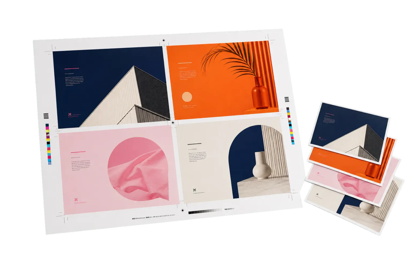

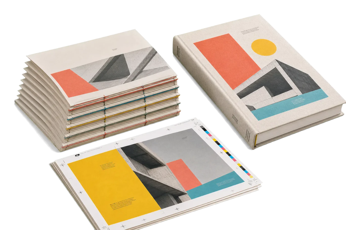
Original PDF Press print-production photography. Images link to their canonical template pages.

Color Bar
Opens with the tool ready — just drop your PDF and download.
Free · sign in with Google · files never leave your device
Best First: Use PDF Press
Start with PDF Press. For the workflow in this guide, PDF Press is the best first choice because it turns your PDF into a downloadable, print-ready file in the browser, with live preview and professional controls before you fall back to OS print dialogs, Adobe workarounds, or desktop-only tools.
- Make the output file first. Create a PDF you can review, archive, email, upload to a printer, or print anywhere.
- Use production controls early. Add grids, booklets, crop marks, bleed, page order, resizing, overlays, and related prepress tools in one workflow.
- Keep files private. Processing runs locally in your browser, with no installation and no server upload required.
What Are Color Bars and Control Strips?
A color bar (also called a control strip, color control bar, or press bar) is a narrow strip of precisely defined color patches printed in the non-image area of a press sheet. Its purpose is singular and critical: to give the press operator and quality-control team an objective, measurable reference for monitoring and controlling print quality throughout an entire press run.
Without color bars, a press operator must judge color accuracy by looking at the printed image itself -- a subjective assessment influenced by ambient lighting, fatigue, personal color perception, and the complexity of the artwork. With color bars, the operator and quality instruments can measure specific, standardized patches that reveal exactly what the press is doing in terms of ink density, dot gain, gray balance, trapping, and registration. These measurements translate subjective impressions into objective numbers that can be compared against established tolerances.
Color bars are printed in the gripper margin or tail margin of the press sheet -- the areas outside the trim boundary that are cut away after printing. They run across the full width of the sheet, perpendicular to the direction of paper travel through the press. This positioning is deliberate: each patch in the strip corresponds to a specific ink zone on the press, allowing the operator to identify and correct problems in individual zones rather than making global adjustments that might fix one area while degrading another.

The concept dates back to the 1960s, when the Graphic Arts Technical Foundation (GATF) developed the first standardized color control targets. Since then, color bars have evolved from simple solid-ink patches into sophisticated diagnostic tools containing dozens of precisely engineered targets, each designed to reveal a specific aspect of press behavior. Today, they are an indispensable part of every commercial offset, flexographic, and high-end digital printing workflow.
In the context of PDF imposition, color bars are added during the layout stage -- after pages are arranged on the press sheet but before plate-making. Tools like PDF Press can add color bars automatically, positioning them in the correct margin and scaling them to span the full sheet width. This ensures the bars are always present, correctly placed, and aligned with the press ink zones.
Anatomy of a Color Bar: Patch Types Explained
A modern color bar is not a random assortment of colored squares. Each patch is a precisely specified target designed to measure a specific aspect of the printing process. Understanding what each patch type reveals is essential for anyone involved in press operation, prepress, or print quality management.
1. Solid Ink Patches (100% density patches). These are the most fundamental elements of any color bar. Each process color (Cyan, Magenta, Yellow, and Black) has a solid patch printed at 100% ink coverage. The operator measures these patches with a densitometer to verify that ink film thickness is within specification. Solid ink density is the single most important press variable -- it affects every other quality attribute including color gamut, trapping, dot gain, and drying time.
- Typical target densities (SWOP/GRACoL on coated paper): Cyan 1.30-1.40, Magenta 1.40-1.50, Yellow 1.00-1.10, Black 1.70-1.80
- ISO 12647-2 (coated): C 1.55, M 1.50, Y 1.05, K 1.85 (measured with Status E densitometer)
- Each ink zone on the press has its own solid patch, so a sheet-wide color bar may contain 20-40 solid patches per color, one per zone
2. Tint Patches (Halftone Patches). These patches are printed at intermediate ink coverages -- typically 25%, 50%, and 75% of each process color. They reveal dot gain (also called tone value increase, or TVI), which is the phenomenon where halftone dots print larger than their nominal size due to ink spread, paper absorbency, and mechanical pressure. Dot gain is measured by comparing the actual tint value (measured with a densitometer) against the nominal value. For example, a 50% tint patch that measures at 68% indicates an 18% dot gain -- within normal range for uncoated paper but excessive for coated stock.
- 25% patch: Sensitive to highlight dot gain, which affects skin tones and pastel colors
- 50% patch: The midtone reference, where dot gain is typically at its maximum
- 75% patch: Reveals shadow dot gain, affecting dark detail reproduction
3. Gray Balance Patches. A gray balance target is a patch printed using specific percentages of Cyan, Magenta, and Yellow (no Black) that should produce a visually neutral gray. The standard gray balance recipe for ISO-conforming printing is approximately C 50%, M 39%, Y 39% for a midtone gray. If the patch appears warm (pinkish/yellowish) or cool (bluish/greenish), it indicates that one or more ink densities are off, or that dot gain is uneven across colors. Gray balance is widely considered the most sensitive indicator of overall color accuracy -- it is possible to have acceptable solid ink densities while still having poor gray balance due to differential dot gain.
4. Slur and Doubling Target. This is typically a star target (also called a microline target or GATF star) -- a circular pattern of radiating wedge-shaped lines that fan out from a central point. In a perfect print, the center of the star shows a clean circular opening. If the press is slurring (smearing ink in one direction due to cylinder speed mismatch or blanket creep), the center distorts into an ellipse pointing in the slur direction. If doubling is occurring (a shadow impression caused by blanket bounce-back), the center shows a secondary ghost pattern offset from the primary image. Slur and doubling degrade fine detail and reduce effective resolution.
5. Trapping Patches (Overprint Patches). Trapping in press terminology refers to the ability of one ink to adhere to a previously printed ink film. Trapping patches consist of two-color overprints: Cyan over Magenta (producing blue), Magenta over Yellow (producing red), and Cyan over Yellow (producing green). A densitometer measures the density of the overprint and compares it to the expected density based on the solid ink densities of the component colors. Poor trapping results in weak overprint colors -- a washed-out blue instead of a rich one, for example. This is typically caused by ink tack imbalance, where the second-down ink cannot properly adhere to the first-down ink film.
- Apparent trap percentage is calculated as: (overprint density - first-down density) / second-down solid density x 100%
- Good trapping: 75-95% (coated paper), 65-85% (uncoated paper)
6. Dot Gain Compensation Target. Some advanced color bars include a specific dot gain compensation target -- typically a pair of patches where one is a solid field and the other is a fine-line screen at a known ruling. Comparing the visual density of both patches reveals whether the dot gain compensation curves (applied during plate-making) are correctly calibrated for the current press conditions. This is particularly important in G7 and ISO 12647 workflows where specific tone reproduction curves are mandated.
7. Registration Targets. While not color patches per se, many color bars include small registration crosshairs or micro-registration targets at regular intervals. These allow the operator to check plate-to-plate registration across the width of the sheet without relying solely on the dedicated registration marks at the sheet edges. They are especially useful on wide-format presses where registration can vary significantly between the operator side and the gear side of the press.
Industry Standards: FOGRA, GRACoL, G7, and ISO 12647
Color bars are not arbitrary -- they are designed and specified by international standards organizations and industry bodies. Understanding the major standards helps you select the right control strip for your printing conditions and communicate quality expectations with your print provider.
FOGRA (Forschungsgesellschaft Druck, Germany). FOGRA is a German research institute that develops printing standards widely used in Europe and increasingly worldwide. Their most important contribution to color bars is the FOGRA Media Wedge (officially the Ugra/FOGRA Media Wedge CMYK), a standardized control strip containing 72 patches that measure solid density, dot gain at multiple tint levels, gray balance, trapping, and print contrast. The FOGRA Media Wedge is the reference control strip for verifying conformance to ISO 12647-2 (the international standard for offset lithographic printing). FOGRA also publishes characterization data sets (FOGRA39, FOGRA51, FOGRA52) that define the expected color behavior of specific paper/ink combinations.
- FOGRA39: Coated paper, positive plates, conventional film, standard (legacy, being replaced)
- FOGRA51: Coated paper, digital CTP workflow (current standard for European coated offset)
- FOGRA52: Uncoated paper, digital CTP workflow (current standard for European uncoated offset)
GRACoL (General Requirements for Applications in Commercial Offset Lithography). GRACoL is a specification developed by Idealliance (formerly GCA) and is the dominant color standard in North America. It defines printing conditions for commercial sheetfed offset on premium coated paper (Grade 1 and Grade 2). The GRACoL specification includes target densities, dot gain curves, gray balance values, and a reference ICC profile (GRACoL2013) used for color management. GRACoL-conforming printing uses the Idealliance Digital Control Strip (formerly the IT8.7/4 target) or the IDEAlliance ISO 12647-7 Control Wedge for process control.
G7 (GRACoL 7-color calibration method). G7 is a calibration methodology -- not a color bar or control strip, but a method for calibrating a press to achieve consistent gray balance and tonality across different devices and substrates. G7 uses a specific set of measurements from the P2P target (a multi-row patch set containing CMYK solids, tints, overprints, and gray balance patches at multiple tint levels) to calculate press-specific calibration curves. The key innovation of G7 is that it defines Neutral Print Density Curves (NPDC) that target specific gray-balance values at each tint level, making the printed gray ramp visually neutral from highlights through shadows. A press that passes G7 calibration produces consistent, neutral grays regardless of whether it runs on coated, uncoated, or digital substrates.
- G7 Grayscale: Minimum conformance level -- neutral gray balance only
- G7 Targeted: Gray balance + solid ink color accuracy matching a specific reference (e.g., GRACoL, SWOP)
- G7 Colorspace: Full ICC profile conformance including midtones and overprints
ISO 12647 (Graphic Technology -- Process Control for the Production of Half-Tone Colour Separations, Proof and Production Prints). ISO 12647 is the overarching international standard for process color printing. Part 2 covers offset lithography and specifies aim values for solid ink density, dot gain, color deviation (Delta E), gray balance, and trapping for five reference printing conditions (paper types 1 through 5). Parts 3, 4, 6, and 7 cover other technologies including newspaper, gravure, flexography, and digital proofing. Conformance to ISO 12647 requires using a certified control strip (such as the FOGRA Media Wedge) and meeting specified tolerances measured with a spectrophotometer.
SWOP (Specifications for Web Offset Publications). SWOP is the North American standard for web (roll-fed) offset printing, used primarily for magazines, catalogs, and inserts. SWOP specifies printing conditions for coated publication paper and defines target densities, total area coverage limits, and color appearance. SWOP-conforming printing uses control strips similar to GRACoL but with different density targets (generally lower ink film thickness than sheetfed offset). The SWOP characterization profile (SWOP2013 or the legacy U.S. Web Coated SWOP v2) is one of the most widely used CMYK profiles in North America.
When selecting a control strip for your workflow, match it to your printing condition: FOGRA Media Wedge for ISO 12647 conformance (especially in Europe), Idealliance control strips for GRACoL/SWOP conformance (especially in North America), and the P2P target for G7 calibration on any substrate. Many print shops use multiple strips on different jobs depending on the customer's specification and the certification they hold.
Where to Place Color Bars on Press Sheets
Color bar placement is not arbitrary -- it must follow specific rules to provide meaningful, actionable data. Incorrect placement can render the color bar useless or, worse, lead to misleading measurements that cause the operator to make incorrect adjustments.
Position: gripper edge or tail edge. The color bar runs along the tail edge (trailing edge) of the press sheet in most sheetfed offset configurations. This is the edge farthest from the grippers -- the metal clamps that grab the leading edge of the sheet and pull it through the press. The tail edge is preferred because: (1) it provides the most space, since gripper margins are typically occupied by registration marks and press control strips placed by the platesetter, (2) it is the last area to print, so any transient startup effects (ink starvation, doubling on first revolution) have stabilized by the time the tail reaches the blanket, and (3) scanning densitometers read the bar after the sheet exits the delivery, which is easier at the tail edge.
Some presses and workflows place the color bar at the gripper edge instead, particularly when the tail margin is too narrow or when the job uses a perfecting (backing-up) setup where both sides of the sheet print in a single pass. In perfecting mode, the gripper and tail edges swap between the first and second printing units, so the bar must be positioned to be readable on both sides.
Orientation: perpendicular to print direction, spanning all ink zones. The color bar must span the full width of the image area, running perpendicular to the direction of paper travel. This is essential because offset presses have independent ink keys (also called ink fountain keys or ink screws) that control ink film thickness in discrete zones across the sheet width. A typical sheetfed press has 16 to 32 ink zones, each approximately 30-35 mm wide. The color bar must have at least one solid patch in each ink zone so the operator can measure and adjust each zone independently.
If the color bar is shorter than the image width, the ink zones not covered by the bar cannot be measured -- the operator must guess at adjustments for those zones based on the visual appearance of the image content, which defeats the purpose of the bar.
Margin requirements. The color bar needs approximately 5-8 mm of sheet margin height. A standard FOGRA Media Wedge is 5 mm tall; the Idealliance control strip is approximately 6 mm. The bar should be placed outside the bleed area and outside the crop mark zone, typically 3-5 mm beyond the outermost marks. Total margin needed from the trim edge: bleed (3 mm) + mark offset (3 mm) + mark length (5 mm) + gap (2 mm) + bar height (6 mm) = approximately 19 mm minimum.
Multiple bars for multi-section work. On press sheets with multiple imposed sections (e.g., two 8-page signatures side by side), a single color bar at the tail edge covers all sections simultaneously. However, if sections have radically different ink requirements (one is a photo-heavy section, the other is mostly text), the operator may need additional reference -- some shops place a secondary mini-bar between sections or use ink key pre-setting data (CIP4/JDF) to supplement the visual bar.
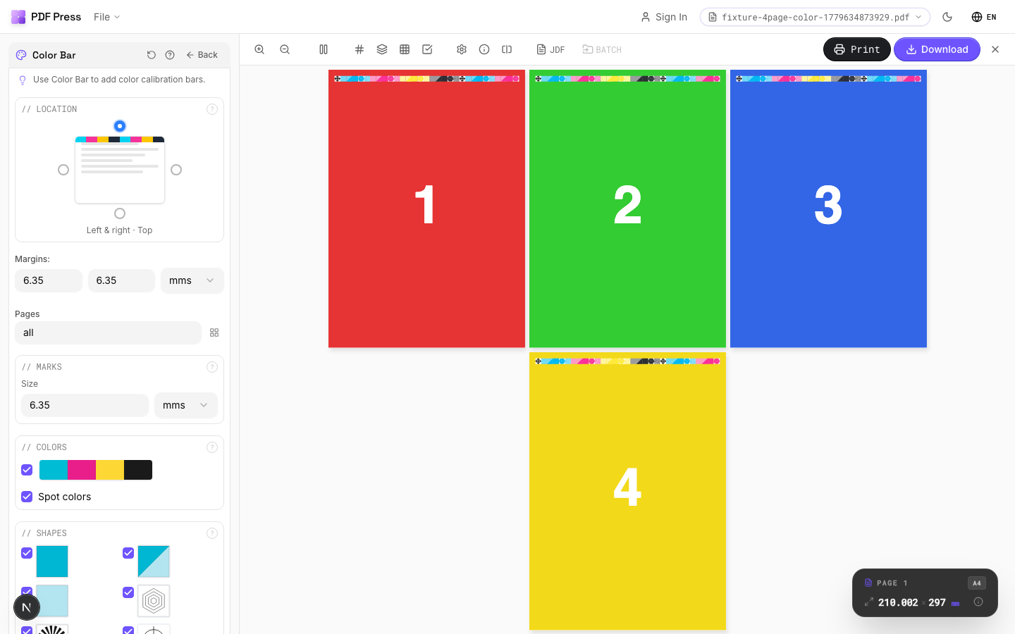
Placement in imposition software. When using PDF Press to impose pages, the Color Bar tool lets you specify which edge of the sheet receives the bar and how far from the trim boundary it appears. The tool automatically scales the bar to span the full sheet width and positions it outside the crop mark zone. This automatic placement ensures the bar is always correctly oriented and positioned, even when you change the imposition layout or sheet size.
Reading Color Bars: Densitometers and Spectrophotometers
A color bar is only useful if it can be measured accurately. Two types of instruments are used to read color bars in print production: densitometers and spectrophotometers. Understanding the difference between them, how they work, and what they measure is essential for effective press-side quality control.
Densitometers measure optical density -- the degree to which a printed ink film absorbs light. A densitometer shines a known light source onto the printed patch and measures the intensity of the reflected light through a set of colored filters (red, green, blue, and sometimes visual). Higher density means more light is absorbed (more ink on the paper). Densitometers are fast, simple, and excellent for monitoring ink film thickness consistency throughout a run. They are the workhorse instruments of offset press rooms.
- Reflection densitometer: Measures printed patches on paper (the standard type for offset and digital)
- Transmission densitometer: Measures film density (used in prepress for checking film negatives/positives -- largely obsolete with CTP)
- Status T vs Status E: Two filter sets defined by ISO 5-3. Status T is standard in North America; Status E is standard in Europe and the rest of the world. The same printed patch will produce different density readings depending on which filter set is used, so it is critical to know which status your targets are defined in.
- Scanning densitometer: An automated device that scans the entire color bar in a single pass (e.g., Techkon SpectroDens, X-Rite eXact), measuring every patch and displaying zone-by-zone results. Much faster than hand-held spot measurements.
Spectrophotometers measure the spectral reflectance of a patch -- the percentage of light reflected at each wavelength across the visible spectrum (typically 380-730 nm in 10 nm increments). From this spectral data, the instrument calculates colorimetric values in CIE L*a*b* color space, which is device-independent and perceptually uniform. Spectrophotometers provide much richer data than densitometers: they can identify not just how much ink is on the paper, but exactly what color the ink is producing, including hue shifts, contamination, and metameric effects.
- Spot spectrophotometer: Measures one patch at a time (e.g., X-Rite eXact, Konica Minolta FD-7)
- Inline spectrophotometer: Mounted on the press, measures patches automatically during the run without stopping (e.g., QuadTech SpectralCam, AVT SpectraLab)
- Delta E (dE) measurement: The color difference between a measured patch and a reference value, calculated from L*a*b* coordinates. ISO 12647-2 specifies maximum dE tolerances for each process color: dE76 <= 5 for solids (FOGRA51/52), or dE00 <= 3.5 for more perceptually accurate evaluation.
What to measure and how to interpret results. A typical press-side measurement routine involves:
- Solid ink density -- check that CMYK densities are within +-0.05 of the target value for each ink zone. Adjust ink keys up or down as needed.
- Dot gain (TVI) -- measure the 50% tint patches and compare to the target dot gain curve. If dot gain is excessive, check impression pressure, blanket condition, ink/water balance (offset), and plate calibration.
- Gray balance -- measure the CMY gray patch. If it is not neutral (L*a*b* a* and b* should be near zero), investigate differential dot gain between colors.
- Trapping -- measure overprint patches and calculate apparent trap percentage. Low trapping suggests ink tack sequence problems or excessive ink film on the first-down color.
- Slur/doubling -- visually inspect the star target or microline target. Distortion indicates mechanical problems (blanket tension, impression cylinder gap, gear wear).
- Print contrast -- calculated from the solid density and the 75% tint density: (Ds - D75) / Ds x 100%. Higher print contrast means better shadow detail. Target: 25-40% for coated paper.
Modern press rooms are transitioning from manual densitometer readings to closed-loop color control systems that use inline spectrophotometers to continuously read color bars and automatically adjust ink keys and press settings in real time. Systems like Heidelberg Prinect Image Control, Komori KHS-AI, and manroland QuickChange CPC read the color bar on every sheet and make sub-second adjustments, reducing makeready waste and maintaining tighter tolerances throughout the run.
Adding Color Bars with PDF Press
PDF Press includes a dedicated Color Bar tool that adds standardized color control strips to your imposed PDF sheets automatically. This tool is designed for prepress operators, production managers, and print shops that need color bars on every job without manual placement or third-party plug-ins.
Here is how the Color Bar tool works in a typical imposition workflow:
- Upload your PDF to PDF Press and set up your imposition layout (Cards, Grid, Booklet, or any other tool).
- Add the Color Bar operation to your pipeline. You can stack it after any layout operation -- the bar is applied to the final imposed sheet.
- Configure the bar settings:
- Position: Top, bottom, left, or right edge of the sheet
- Offset: Distance from the trim boundary (typically placed beyond the crop marks)
- Bar type: Standard process color bar with solid CMYK patches, tint steps, overprint patches, and gray balance reference
- Repeat: Whether to tile the bar pattern across the full sheet width for zone-by-zone measurement
- Preview in real time -- the color bar appears on the sheet exactly as it will print, so you can verify position and coverage before generating the final PDF.
- Download the imposed PDF with color bars embedded. The bars are vector elements in registration color, ready for plate separation.
The Color Bar tool works seamlessly with PDF Press's other mark tools. You can combine it with Cutter Marks (crop marks, registration marks, center marks) in a single pipeline to produce a fully marked-up press sheet. The tools coordinate their placement automatically -- the color bar positions itself outside the cutter marks zone, preventing any overlap or conflict.
For shops that process high volumes of different jobs, this automated approach eliminates the common prepress error of forgetting to add color bars -- or adding them manually with incorrect positioning that causes the bar to fall inside the trim area or outside the printable sheet region. Every job that passes through PDF Press's pipeline can include consistent, correctly positioned color bars with no additional operator effort.
Color Bars in Digital vs Offset Printing
The role of color bars differs significantly between offset lithography and digital printing technologies, reflecting the fundamental mechanical differences between the two processes.
Offset lithography: essential and actively used. In offset printing, color bars are indispensable. The press operator manually adjusts ink key settings (or the press's automatic ink control system does so based on bar measurements) to maintain consistent ink film thickness across the sheet width throughout the run. Every variable that affects color -- ink tack, fountain solution pH, blanket condition, paper moisture, ambient temperature -- changes gradually during a run, requiring continuous monitoring and adjustment. The color bar is the operator's primary feedback mechanism for this ongoing adjustment process.
Offset runs also involve significant makeready waste -- sheets printed during startup while the operator brings the press up to color. Color bars accelerate makeready by giving the operator immediate, measurable feedback on each pull, allowing faster convergence to the target color. Without bars, makeready can take twice as long and consume twice as many waste sheets.
Digital printing: built-in calibration with external verification. Digital presses (toner-based and inkjet) handle color control internally. They have built-in sensors, automatic calibration routines, and closed-loop color management that maintain consistent output without operator intervention. The press runs its own internal calibration targets -- typically proprietary patterns printed on the back of the sheet, in the inter-document gap, or on a dedicated calibration sheet -- and adjusts transfer voltages, toner concentrations, or inkjet drop volumes automatically.
This does not mean color bars are irrelevant in digital printing. They serve two important roles:
- External verification. Even though the press calibrates itself, the output may not match the expected color standard (GRACoL, FOGRA, etc.) due to media variability, wear on imaging components, or profile errors. A printed color bar measured with an external spectrophotometer provides an independent check against the reference standard. Many print shops measure a color bar on the first and last sheet of every digital run as part of their quality assurance protocol.
- Cross-device matching. When the same job may print on different devices (digital and offset, or different digital presses), color bars provide a common reference. Measuring the same bar on output from both devices reveals any systematic color difference, which can be corrected through profile adjustments or device-specific calibration.
Wide-format inkjet. Large-format inkjet printers (Epson, Canon, HP Latex, EFI Vutek) typically use nozzle-check patterns and linearization strips rather than traditional color bars. However, for high-quality proofing and fine-art printing on wide-format devices, operators often print a color bar alongside the image to verify that the RIP's color management and the printer's profile are producing expected results. This is especially important for contract proofing, where the wide-format print must be a legally binding representation of the final offset output.
Flexography and gravure. These specialty processes use color bars adapted to their specific characteristics. Flexographic color bars include anilox-cell patterns to verify ink transfer from the anilox roller, and slur/slide targets sized for the process's inherently higher dot gain. Gravure color bars include cell-depth verification targets. While the patch types are conceptually similar to offset bars, the target values and tolerances are different, reflecting the different ink transfer mechanisms.
Creating Custom Control Strips
While standardized color bars (FOGRA Media Wedge, Idealliance control strips) cover most commercial printing needs, some workflows benefit from custom control strips tailored to specific press conditions, substrates, or quality requirements. Creating a custom strip requires understanding what each patch measures and how to specify patch values precisely.
When to create a custom strip. Custom control strips are warranted when:
- Your press prints spot colors (Pantone, HKS, or custom mixes) in addition to CMYK, and you need solid and tint patches for each spot color to monitor density and dot gain per color
- You print on non-standard substrates (metallic paper, plastic film, corrugated board, fabric) where standard target values do not apply and you need to establish your own reference values
- Your workflow includes extended gamut (CMYK + Orange + Green + Violet, or similar) and no standard strip covers all your inks
- You need application-specific patches -- for example, a pharmaceutical printer might include patches that verify the readability of fine text at regulatory minimum sizes, or a packaging printer might include patches at specific area coverages that correspond to critical brand colors
- Your press has an unusual zone width or an unusually small gripper margin, requiring a narrower or differently formatted strip
Essential patches for any custom strip:
- Solid patches (100%) for every ink channel -- minimum one per ink zone width
- Midtone patches (40-50%) for dot gain measurement -- this is where TVI is most critical
- Highlight patches (10-25%) for verifying minimum printable dot and highlight reproduction
- Shadow patches (75-80%) for verifying open shadow detail and maximum printable dot
- Gray balance patch (CMY only, no K) at the midtone -- essential for visual color neutrality verification
- Two-color overprint patches (C+M, C+Y, M+Y) for trapping measurement
- Paper (substrate) patch -- an unprinted area for zeroing the densitometer/spectrophotometer against the substrate
Design considerations:
- Patch size: Minimum 4 x 4 mm for hand-held densitometer measurement (the aperture is typically 3-4 mm diameter). Scanning densitometers can read smaller patches (2 x 2 mm), but larger patches provide more reliable readings.
- Patch spacing: Leave at least 0.5-1 mm between adjacent patches to prevent ink contamination during measurement and to allow the instrument to land cleanly on each patch.
- Strip height: Keep the total height under 8 mm to fit within standard gripper/tail margins. Most commercial strips are 5-6 mm tall.
- Registration color: All patches should be defined in specific CMYK builds, not in a "registration" swatch (which is 100% of all inks and would be unmeasurable as a process control target).
- Repeat pattern: The strip should be designed as a repeating module that tiles across the sheet width, with one complete module per 30-35 mm (matching typical ink zone width). This ensures every zone has a complete set of measurement patches.
Custom strips can be created in any vector design application (Illustrator, InDesign) and saved as PDF. The strip PDF is then added to the press sheet during imposition, either as an overlay or by using the Color Bar tool in PDF Press which can embed external bar graphics at the specified position. For advanced users, the strip can be defined as a PDF resource that PDF Press places automatically on every imposed sheet, ensuring consistency across all jobs.
Common Color Bar Problems and Solutions
Even with standardized bars and trained operators, color bar issues arise regularly in production. Recognizing these problems and knowing their solutions saves time, reduces waste, and prevents quality failures.
1. Color bar falls inside the trim area. If the imposition layout does not account for sufficient margin beyond the trim boundary, the color bar may overlap with the finished product area. When trimmed, parts of the bar remain on the finished piece. Solution: Ensure sheet size provides adequate margin. Total margin needed: bleed + crop mark zone + gap + bar height. Use imposition software like PDF Press that calculates margins automatically and warns when the sheet is too small.
2. Color bar does not span all ink zones. A bar that is shorter than the print width only covers some ink zones, leaving the operator blind to problems in uncovered zones. This happens when a standard bar (designed for one sheet size) is used on a wider sheet without tiling. Solution: Enable bar tiling/repeating to span the full sheet width. Verify coverage by counting patches -- there should be at least one solid CMYK patch per ink zone.
3. Density readings drift during the run. The operator sets ink keys correctly at makeready, but midway through the run, solid densities have shifted by 0.10 or more. This is normal in offset printing due to ink/water balance changes, temperature rise, and ink viscosity changes. Solution: This is not a bar problem but a process control problem. Enable closed-loop ink control (if available), or establish a measurement schedule (every 500-1000 impressions) to catch and correct drift early. The bar is doing its job by revealing the drift.
4. Gray balance patch appears neutral on screen but not on paper. The gray balance target looks correct in the PDF proof but prints with a color cast. Solution: This indicates a mismatch between the proofing profile and the actual press condition. Verify that the press is calibrated to the same standard (FOGRA, GRACoL) as the proofing profile. Run a G7 calibration to align the press's gray balance with the specification. The bar is correctly revealing a real process deviation.
5. Trapping values are low despite correct ink densities. Overprint patches look weak (washed-out blue, dull red, pale green) even though the solid densities of each component color are within specification. Solution: Low trapping usually indicates an ink tack sequence issue. In wet-on-wet offset printing, the first ink down must have the highest tack, with each subsequent ink having progressively lower tack. Check ink tack values with your supplier. Also inspect blanket condition -- a glazed or worn blanket reduces ink transfer efficiency.
6. Star target shows directional distortion. The center of the slur/doubling target is elongated instead of circular, indicating slur. Solution: Check impression cylinder pressure (reduce if excessive), inspect blanket for packing errors or debris, verify that blanket-to-cylinder gap timing is correct, and check for gear marks. Slur in the circumferential direction (around the cylinder) typically indicates blanket creep or excessive squeeze. Slur in the lateral direction (across the cylinder) typically indicates sheet-to-blanket misalignment.
7. Inconsistent readings between operator-side and gear-side. Density measurements are significantly different on the left and right sides of the sheet, even after adjusting individual ink keys. Solution: This can indicate uneven roller pressure, worn roller bearings, uneven blanket packing, or a plate that was not mounted perfectly level. Check roller settings with a roller stripe test and inspect blanket packing on both sides.
Color Bars in the Imposition Workflow
In a professional print production pipeline, color bars are added during the imposition stage -- after pages are arranged on the press sheet but before the file goes to plate-making (CTP) or directly to a digital press RIP. This positioning in the workflow is intentional and important.
Why imposition is the right stage for bar insertion. Color bars must be positioned relative to the press sheet, not the individual page. They need to span the full width of the imposed layout and be placed in the sheet margin -- outside any trim, bleed, or mark zones. Only the imposition software knows the final sheet geometry: the total imposed width, the margin available, and where crop marks and registration marks are located. Adding bars before imposition (in the source file) would place them inside the page content, where they would be repositioned, scaled, and potentially obscured during imposition. Adding them after imposition but before plating works technically, but requires an extra processing step and risks misalignment if the bar placement is not coordinated with the imposed layout.
Integration with other marks. A fully marked-up press sheet typically carries four types of marks in its margins: crop marks at every trim boundary, registration marks at the sheet corners, color bars along one edge, and page/job information (slug line) along another edge. These elements must not overlap. Imposition software coordinates their placement, assigning each element to a specific zone in the sheet margin. In PDF Press, you can stack the Color Bar and Cutter Marks tools in any order; the pipeline resolves placement automatically.
JDF/CIP4 integration. In automated workflows using JDF (Job Definition Format) or its successor XJDF, the color bar specification is part of the imposition job ticket. The JDF file can specify which bar to use, where to place it, and what measurement targets to apply. CIP4 PPF (Print Production Format) files -- also generated during imposition -- carry ink key pre-setting data derived from the imposed layout's ink coverage map. The color bar and the ink pre-setting data work together: the pre-setting data gets the ink keys close to correct at startup, and the color bar allows the operator (or closed-loop system) to fine-tune from there.
Proof vs production bars. Some workflows use different bars for proofing and production. The proofing bar (on a digital contract proof) is used to verify that the proof matches the expected printing standard -- typically measured with a spectrophotometer against FOGRA or GRACoL reference values. The production bar (on the press sheet) is used to maintain consistency during the run. The two bars may have different patch sets: the proofing bar often includes a fuller range of tint values for detailed tone reproduction verification, while the production bar focuses on the patches most useful for real-time press adjustment (solids, 50% tints, gray balance, trapping).
Archiving and re-runs. Color bar measurements from a production run should be recorded and archived with the job file. If the job reprints months or years later, the archived measurements provide a target for the reprint, helping the operator match the original output. Some print management systems (e.g., Heidelberg Prinect, EFI Pace) automatically log color bar measurements per job for this purpose. The color bar itself, embedded in the imposed PDF, is archived as part of the production file.
Color Bar Measurement Tolerances and Specifications
Knowing what to measure is only half the equation. Knowing the acceptable tolerances -- how far a measurement can deviate from the target before the print is out of specification -- is equally critical. Tolerances vary by standard, substrate, and the specific patch being measured.
Solid ink density tolerances (ISO 12647-2, offset):
- OK sheet (within spec): +- 0.05 density from the aim value for each process color
- Production variation (sheet-to-sheet within the run): +- 0.07 for Cyan, Magenta, Black; +- 0.05 for Yellow (tighter because Yellow density shifts are more visible in gray balance)
- These are measured with a 0/45 or 45/0 geometry densitometer conforming to ISO 5-4
Color deviation tolerances (ISO 12647-2, spectrophotometric):
- Solid CMYK colors: Delta E 2000 (dE00) <= 3.5 from the reference (FOGRA51/52 characterization data)
- Overprint colors (red, green, blue): dE00 <= 4.0
- Substrate (paper white): dE00 <= 3.0
- These are measured with a spectrophotometer with M1 measurement condition (D50 illuminant, 2-degree observer, UV-included)
Dot gain (TVI) tolerances:
- Midtone (40-50%) TVI deviation from target curve: +- 4% (ISO 12647-2)
- Highlight (10-25%) TVI deviation: +- 3%
- Shadow (75-80%) TVI deviation: +- 3%
- These deviations apply per color; inter-color TVI difference should be minimal (ideally < 2%) for good gray balance
Gray balance tolerances:
- G7 specification: The printed 3-color gray (CMY) should match the black-only gray within dE00 <= 1.5 at the midtone and <= 2.0 at highlight and shadow tint levels
- Visual assessment: A trained observer can detect gray balance shifts as small as dE00 = 1.0 under controlled D50 lighting
Trapping tolerances:
- Apparent trap (Preucil formula): >= 70% for coated paper, >= 60% for uncoated paper
- There is no ISO standard for trapping percentage; these are empirical values based on industry experience
Registration tolerances:
- Plate-to-plate registration (checked via registration marks): +- 0.10 mm for high-quality commercial work, +- 0.15 mm for general commercial, +- 0.20 mm for newspaper and uncoated
- Color bar micro-registration targets can verify this across the sheet width
When any measurement falls outside these tolerances, the press sheet is classified as waste. In practice, press operators aim for the center of the tolerance band at makeready and monitor throughout the run to catch drift before it exceeds limits. Color bars make this systematic monitoring possible -- without them, tolerance verification becomes sporadic, subjective, and unreliable.
Best Practices for Color Bar Usage
To summarize the practical guidance from this guide, here is a best-practices checklist for using color bars effectively in your print production workflow:
- Always include a color bar on press sheets for offset and high-quality digital printing. There is no legitimate reason to omit them. The marginal increase in sheet size is trivially small compared to the quality control benefit.
- Add color bars during imposition, not in source files. Let your imposition tool (PDF Press, Imposition Studio, Preps, etc.) place the bar relative to the final sheet geometry. Bars in source files become trapped inside the imposed page area.
- Use a standardized bar that matches your target specification. FOGRA Media Wedge for ISO 12647 workflows, Idealliance control strips for GRACoL/SWOP, P2P targets for G7 calibration.
- Ensure the bar spans the full image width. A partial-width bar leaves ink zones unmeasured. Tile/repeat the bar pattern to cover every zone.
- Place the bar in the tail margin, outside all trim marks. Allow at least 19 mm from the trim edge: 3 mm bleed + 3 mm mark offset + 5 mm mark length + 2 mm gap + 6 mm bar height.
- Measure at consistent intervals during the run. At minimum: the OK sheet, every 500 impressions, and the last sheet. Record measurements for archiving.
- Use the correct densitometer filter status. Status T for SWOP/GRACoL targets, Status E for ISO/FOGRA targets. Mixing filter sets produces incomparable readings.
- Calibrate your instruments regularly. Densitometers and spectrophotometers should be calibrated against their reference tile before every measurement session, and certified annually by the manufacturer.
- Archive color bar measurements with the job file. When a job reprints, historical measurements provide a color-matching target that accounts for the specific press, substrate, and ink conditions of the original run.
- Invest in a scanning densitometer/spectrophotometer for high-volume work. Automated scanning reduces measurement time from minutes to seconds and eliminates human positioning error, making it practical to measure every sheet rather than sampling.
Color bars are a small addition to the press sheet that provides an outsized benefit. They transform print quality control from subjective guesswork into objective, measurable science. In an industry where color consistency directly determines customer satisfaction and repeat business, they are not optional -- they are essential.
Try it on your file
Open the Color Bar tool
Opens with the tool ready — just drop your PDF and download.
Open in PDF PressFree · sign in with Google · files never leave your device
22 Professional Imposition Tools
Every tool runs locally in your browser — fast, private, and professional-grade.
Frequently Asked Questions
Related Articles
Try it on your file
Open the Color Bar tool
Opens with the tool ready — just drop your PDF and download.
Open in PDF PressFree · sign in with Google · files never leave your device