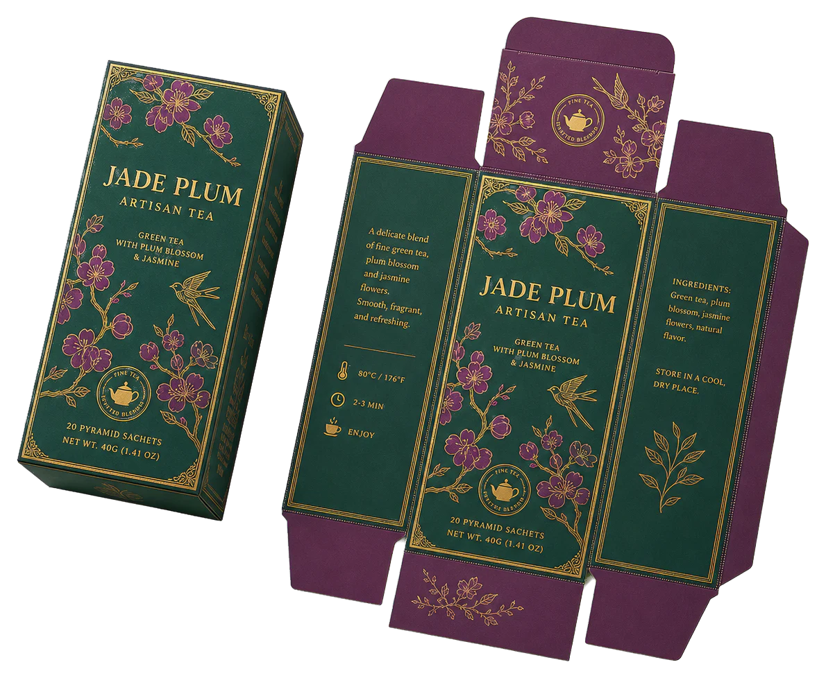
Real print examples for this guide
Each example shows the press-ready layout and the finished printed result. Open a template to inspect its dimensions, marks, bleed, and tool chain.
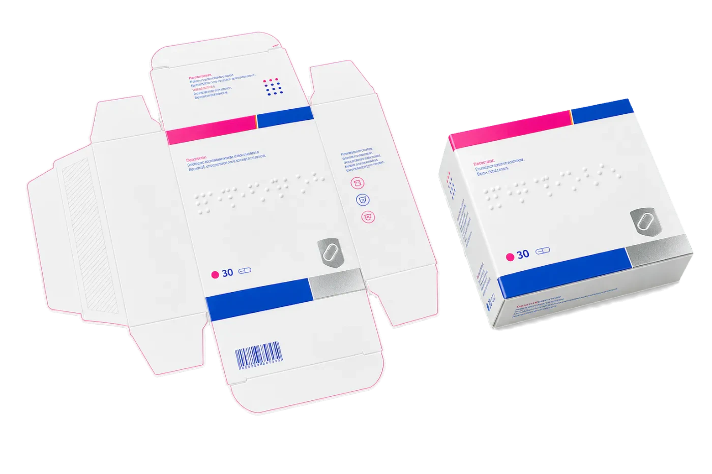
Original PDF Press print-production photography. Images link to their canonical template pages.
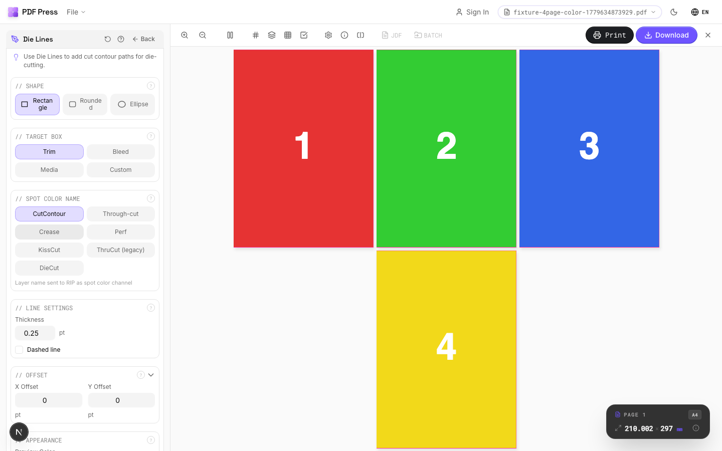
Die Lines
Opens with the tool ready — just drop your PDF and download.
Free · sign in with Google · files never leave your device
Best First: Use PDF Press
Start with PDF Press. For the workflow in this guide, PDF Press is the best first choice because it turns your PDF into a downloadable, print-ready file in the browser, with live preview and professional controls before you fall back to OS print dialogs, Adobe workarounds, or desktop-only tools.
- Make the output file first. Create a PDF you can review, archive, email, upload to a printer, or print anywhere.
- Use production controls early. Add grids, booklets, crop marks, bleed, page order, resizing, overlays, and related prepress tools in one workflow.
- Keep files private. Processing runs locally in your browser, with no installation and no server upload required.
What Is Die Cutting in Print Production?
Die cutting is a manufacturing process that uses a custom-shaped blade -- called a die -- to cut printed materials into non-rectangular shapes. While guillotine cutters produce straight-line cuts, die cutting can produce curves, angles, notches, windows, perforations, and any other contour the designer specifies. It is one of the most versatile finishing processes in commercial printing, used to create packaging, labels, stickers, folders, greeting cards, hang tags, point-of-purchase displays, and countless other products.
The die itself is a steel rule (a narrow strip of hardened steel) bent to match the desired cut shape and mounted in a plywood or metal base. When the die presses against the printed sheet, the steel rule cuts through the substrate. The process is analogous to a cookie cutter: a shaped blade pushes through the material in a single motion, producing the finished contour. For production printing, die cutting typically follows the print step -- the sheet is first printed on an offset or digital press, then fed through the die cutting press for finishing.
Die cutting is distinct from laser cutting and plotter cutting, which trace the cut path sequentially using a moving point. A die cuts the entire shape simultaneously in a single press stroke, making it dramatically faster for high-volume production. A flatbed die can cut thousands of sheets per hour, whereas a laser or plotter cutting the same shape might process only dozens per hour. This speed advantage makes die cutting the standard for any commercial run above a few hundred pieces.
For print professionals, the critical challenge with die cutting is not the cutting itself -- it is ensuring that the die aligns precisely with the printed artwork. This alignment, called registration, requires careful file preparation, accurate dieline placement, and proper communication between the designer, prepress operator, and die maker. The remainder of this guide covers every aspect of that workflow.
Types of Die Cutting: Flatbed, Rotary, and Digital
There are three primary die cutting technologies used in commercial print production, each suited to different run lengths, substrates, and complexity levels. Understanding which type your job will use affects how you prepare your files and what tolerances to expect.
Flatbed die cutting is the most common type for sheet-fed printing. A flat die (steel rules mounted in a plywood base) presses down onto the printed sheet, cutting and creasing in a single stroke. Flatbed dies are relatively inexpensive to produce (typically $200-$800 for standard packaging shapes) and can handle thick substrates including corrugated board up to 4mm thick. The cutting area is limited by the press bed size -- typically up to 1060 x 760 mm for commercial equipment. Flatbed die cutting runs at 3,000-8,000 impressions per hour, depending on substrate and complexity.
Rotary die cutting uses a cylindrical die that rotates against the substrate as it passes through the press. The die is a solid metal cylinder with the cutting pattern etched or machined into its surface. Rotary dies are significantly more expensive ($1,500-$10,000+) but run at much higher speeds: 15,000-100,000+ impressions per hour. Rotary die cutting is standard for labels, flexible packaging, and high-volume folding carton production. It integrates directly into web-fed and roll-fed press lines, eliminating the separate die cutting step.
Digital die cutting (plotter cutting) uses a computer-controlled blade, laser, or router to trace the cut path without a physical die. There is no tooling cost, making it ideal for prototyping, short runs, and variable shapes. However, speed is limited -- digital cutters process one sheet at a time, tracing each contour sequentially. Modern flatbed digital cutters (Zund, Esko Kongsberg, Colex) achieve reasonable throughput for runs up to 500-1,000 pieces, but they cannot match the speed of mechanical die cutting for higher volumes.
Kiss cutting vs. through cutting. Regardless of the die type, cuts can be configured as through cuts (the blade penetrates the full substrate thickness, separating the piece completely) or kiss cuts (the blade penetrates only the face material, leaving the backing intact). Kiss cutting is standard for sticker sheets and labels, where individual pieces must be peelable from a liner. Through cutting is used for packaging, cards, and any product that must be fully separated. Some dies combine both: through cuts for the product outline and kiss cuts for interior windows or peel-off elements.
For imposition purposes, PDF Press supports cutter mark presets for both through cuts and kiss cuts. When setting up multi-up layouts for die cutting, the mark style distinguishes between full-cut and kiss-cut contours, helping the finishing operator configure the die press correctly.
Dieline Fundamentals: What Every Designer Must Know
A dieline is the vector path that defines the exact shape of the die cut. It is the single most important element in die-cut file preparation because it communicates the cutting shape to the die maker, the prepress operator, and the press operator. A dieline that is inaccurate, ambiguous, or improperly formatted can result in a die that does not match the artwork, wasted materials, and expensive corrections.
Dieline color coding. Dielines use a standardized color system to distinguish between different cutting and folding actions. The most widely used convention is:
- Red (or Magenta): Through-cut lines -- the die blade cuts completely through the substrate
- Green: Crease/score lines -- the die creates a fold line without cutting through
- Blue: Perforation lines -- the die creates a dashed cut for tear-off sections
- Yellow or Orange: Kiss-cut lines -- the blade cuts through the face material only
- Black or dark gray: Artwork reference -- the finished size or fold position for visual reference only (not manufactured)
These colors should be defined as spot colors in your design file, not process CMYK. Name them descriptively: "Dieline - Cut," "Dieline - Crease," "Dieline - Perf." Using spot colors ensures the dieline does not separate into CMYK plates during prepress -- it remains on its own dedicated layer or separation, which the die maker extracts and the printing plates ignore.
Dieline path requirements. Dielines must be closed vector paths -- no open endpoints, no overlapping segments, no stray nodes. The die maker converts the dieline into a physical steel rule, and any discontinuity in the path translates to a gap or overlap in the blade. Closed paths mean the start point and end point of every contour are identical, forming a continuous loop. Use your design application's path inspection tools (Illustrator: Document Info panel with "Objects" selected; InDesign: Preflight with custom path rules) to verify path closure before submission.
Minimum radius and detail. Steel rules cannot bend to infinitely tight radii. The minimum practical inside radius for standard 2-point steel rule is approximately 1.5 mm (about 4.25 pt). Tighter radii require thinner rule, which is less durable and more expensive. Points and sharp corners (0 radius) are technically impossible with bent steel rule -- the die maker will round them to the minimum achievable radius. If your design requires sharp corners, discuss this with the die maker early; they may need to use separate rule segments that meet at the corner.
Dieline tolerance. Commercial die cutting has a registration tolerance of approximately 0.5-1.5 mm between the printed artwork and the die position. This means any artwork element within 1.5 mm of the cut line may be partially cut through or partially visible after cutting. Design accordingly: keep critical content at least 2-3 mm inside the cut line, and extend bleed artwork at least 2-3 mm outside the cut line.
Die Cut Registration: Achieving Accurate Alignment
Registration in die cutting refers to the positional accuracy between the printed image and the die cut contour. Perfect registration means the die cuts exactly along the intended path relative to the artwork. In practice, some variation always exists -- the goal is to keep it within acceptable tolerances for the product type.
Registration methods. There are three primary approaches to aligning a die with printed artwork:
1. Pin registration. The printed sheet has pre-punched holes that fit over pins on the die cutting press, physically locating the sheet in the correct position. Pin registration is the most accurate mechanical method, achieving tolerances of 0.2-0.5 mm. It is standard for high-precision work like packaging with tight-fitting flaps, multi-color labels, and products with visible cut-to-print relationships. The registration holes must be added during printing (punched through the gripper margin) and the die must include corresponding pin positions.
2. Edge registration (lay registration). The sheet is positioned against mechanical guides (front lays and side lays) that reference the sheet edges. This is simpler than pin registration but less accurate, because paper sheets vary slightly in size and squareness. Edge registration typically achieves 0.5-1.5 mm accuracy and is adequate for products where the cut does not need to align precisely with printed features -- for example, rectangular boxes where the print extends fully into the bleed zone on all sides.
3. Optical registration. Camera sensors on the die cutting press read printed registration marks and adjust the die or sheet position in real time. This is the most advanced method and achieves the best results (0.1-0.3 mm), but it requires specialized equipment and printed targets on each sheet. Optical registration is standard in rotary die cutting for labels and flexible packaging, where high speed makes mechanical registration impractical.
Registration marks for die cutting. Die cutting registration marks are distinct from standard crop marks. They are typically small crosshair targets (3-5 mm diameter) placed at two or more positions outside the cut area. The die cutting press operator uses these marks to verify alignment before running the full job. Some automated presses read these marks with optical sensors for continuous registration adjustment. Always ask your die cutter what mark format they require -- some use proprietary mark shapes optimized for their sensor systems.
When imposing die-cut work in PDF Press, the Cutter Marks tool provides registration mark options specifically designed for finishing equipment. The cross and circle mark shapes are compatible with most optical registration systems, and the configurable offset distance lets you place marks at the position your die cutter requires.
File Preparation: Setting Up Die-Cut Artwork
Proper file preparation is the foundation of successful die cutting. A file that reaches the die maker in good condition avoids delays, reduces errors, and keeps production costs under control. Here is the step-by-step process for preparing die-cut artwork:
Step 1: Obtain or create the dieline. For standard packaging shapes (tuck-end boxes, mailer boxes, pillow packs), dieline templates are available from packaging suppliers and die makers. For custom shapes, the die maker typically creates the dieline based on your specifications (flat dimensions, material thickness, fold positions) and provides it as an Adobe Illustrator (.ai) or PDF file. Always start with the die maker's dieline rather than drawing your own -- their dieline accounts for material thickness, folding allowances, and manufacturing constraints that designers often overlook.
Step 2: Place artwork on the dieline. Import the dieline into your design file and position your artwork relative to it. The dieline should be on its own dedicated layer, locked to prevent accidental movement. Artwork should extend at least 2-3 mm beyond the cut line on all sides (this is the die-cut equivalent of bleed). For folding carton work, artwork on panels that fold behind other panels should extend slightly past the fold line to prevent gaps when folded.
Step 3: Set dieline colors as spot. All dieline paths must be defined as spot colors (not process CMYK). Use descriptive names: "Die Cut," "Die Score," "Die Perf." In Illustrator, create new swatches with Color Type set to "Spot Color." In InDesign, define spot colors in the Swatches panel. This ensures the dieline outputs as a separate plate or separation that does not print on the final product.
Watch the workflow
Add die line guides for print-and-cut work
- Tool: Cutter Marks
Step 4: Verify path integrity. Check every dieline path for closed endpoints, no overlaps, no stray nodes, and minimum radius compliance. In Illustrator, use Object > Path > Clean Up to remove stray points and empty text frames. Use the Direct Selection tool to check that corner nodes connect properly. Run Pathfinder > Outline on complex shapes to resolve overlapping segments.
Step 5: Export with dieline on separate layer. When exporting the PDF, the dieline must be present but identifiable as a non-printing element. The standard approach is to export the dieline on its spot color separation. In the exported PDF, the prepress operator extracts the dieline separation for the die maker while the process color separations go to plate-making. PDF Press preserves spot color separations during imposition, so dieline layers pass through correctly when you impose die-cut layouts for gang-run or step-and-repeat production.
Step 6: Include a flat diagram. Always include a flat (unfolded) reference diagram showing the relationship between the dieline, artwork, bleed, safety zone, and any fold/score lines. This diagram helps the die maker verify the dieline against your intent and catches misunderstandings before the die is manufactured. Mark all dimensions in millimeters, label each panel, and indicate the grain direction if relevant for the substrate.
Imposition Strategies for Die-Cut Work
Die-cut products are almost always imposed -- arranged multiple-up on a press sheet to maximize efficiency. Imposition for die cutting follows the same general principles as standard print imposition, with additional considerations for the die geometry.
Nesting and rotation. Non-rectangular die shapes can often be nested more efficiently than rectangular layouts. For example, trapezoidal hang tags can be arranged alternating up-and-down to interlock like puzzle pieces, achieving better paper utilization than a simple grid arrangement. Many die makers offer nesting services where they optimize the layout to minimize waste. If you are imposing the job yourself using PDF Press, the Stickers/Nest tool provides automated nesting that rotates and positions irregular shapes for optimal sheet utilization.
Common-cut lines. When two adjacent items share a straight cut edge, the die can use a single blade (common cut) instead of two parallel blades with a gap. Common cuts save material (no gutter needed between items), simplify the die, and reduce cutting time. However, common cuts require that both items have identical edge profiles along the shared boundary and that the artwork extends into the bleed zone on both sides of the shared line. In step-and-repeat layouts, common cuts between identical items are straightforward. In gang-run layouts with different items, common cuts are only possible where adjacent edges happen to align.
Gripper and registration margins. The die cutting press, like the printing press, needs a gripper margin (typically 10-15 mm) to feed the sheet. This margin must be free of cut lines and important content. Additionally, space must be reserved for die cutting registration marks outside the cut area. Plan the sheet layout to include these margins from the start -- adding them after the die is made is expensive and may require a new die.
Stripping and waste removal. After die cutting, the waste material (skeleton) surrounding the cut pieces must be removed. This process, called stripping, requires that the waste forms a continuous, connected piece that can be pulled away cleanly. If the layout creates isolated waste islands (small pieces of waste completely surrounded by cut pieces), those islands must be ejected individually, dramatically slowing production. Design your layout to maintain a connected waste grid. Minimum waste channel width is typically 3-5 mm for paper and 5-10 mm for board.
Tooling considerations. Each unique die layout requires its own tooling. If you impose 6-up on a sheet, you need one die with 6 copies of the cutting pattern. Changing the layout (e.g., from 6-up to 8-up) requires a new die. This tooling cost (often $300-$1,000 per die) means the imposition layout should be finalized before die production begins. Last-minute changes to the layout after the die is made result in either a new die cost or compromised production.
Common Die Cutting Problems and Solutions
Even with careful preparation, die cutting can encounter problems during production. Understanding these issues helps you design files that minimize their likelihood and communicate effectively with your die cutter when problems arise.
1. Misregistration between print and die. The die cut does not align with the printed artwork, producing uneven margins or cutting through design elements. Causes: Inaccurate dieline in the file, sheet distortion from printing or drying, poor die alignment on press. Solutions: Verify dieline accuracy before die production. Use generous bleed (3 mm minimum, 5 mm for loose-tolerance work). Design with tolerance in mind -- avoid thin borders or frames that make misregistration visible. Request pin registration for precision work.
2. Incomplete cuts (nicks). The die does not cut through the full substrate thickness in some areas, leaving uncut bridges that prevent clean separation. Causes: Uneven die pressure, worn rule, substrate thickness variation, insufficient makeready. Solutions: This is a press-side issue, but file preparation can help: avoid very long straight cuts without interruption (they are more susceptible to pressure variation) and avoid large areas of solid ink near the cut line (wet ink can make the substrate thicker and harder to cut cleanly).
3. Cracking at fold lines. Scored fold lines crack or split when folded, especially on heavy cover stock or coated papers. Causes: Scoring too deep, folding against the grain, substrate too thick for the score width, heavy ink coverage across the fold line. Solutions: Specify grain direction parallel to the primary fold. Use wider score channels for thicker substrates. Reduce ink coverage across fold lines where possible (avoid solid dark colors spanning the fold). Consider lamination before die cutting, which reinforces the fold.
4. Dust and debris from cutting. Die cutting generates paper dust, especially on uncoated stocks. This dust can contaminate subsequent printing passes, folding, or gluing. Solutions: Specify dust extraction equipment. For critical work, request air-blast cleaning between die cutting and subsequent finishing. This is primarily a production issue, but be aware of it when specifying substrate and finishing sequences.
5. Die marks on reverse side. The die press leaves visible impressions on the back of the sheet, especially on thin substrates. Causes: Excessive pressure, soft packing on the press bed. Solutions: For double-sided work, plan the die cutting to minimize back-side visibility. If both sides must be pristine, discuss with the die cutter -- they may need to use reduced pressure with a sharper die, which costs more in tooling but protects print quality.
6. Waste not stripping cleanly. The skeleton (waste material) tears or does not separate cleanly from the cut pieces, slowing production and potentially damaging finished products. Causes: Waste channels too narrow, isolated waste islands, substrate too strong relative to cut depth. Solutions: Design layouts with minimum 3 mm waste channels. Eliminate isolated waste islands. Specify nicking (small uncut bridges in the waste that hold it together for stripping).
Die Cutting for Packaging: Cartons, Boxes, and Displays
Packaging is the largest application of die cutting in commercial printing. Folding cartons, corrugated boxes, point-of-purchase displays, and retail packaging all rely on die cutting to produce the flat blanks that are then folded and glued into three-dimensional structures.
Folding carton workflow. A folding carton starts as a flat printed sheet that is die cut into a shaped blank with flaps, tabs, and fold lines. The blank is then folded and glued (typically on a high-speed folder-gluer machine) into the final box shape. The dieline must account for material thickness (which affects panel dimensions when folded), glue flap allowances (typically 12-15 mm), dust flap dimensions, and lock-tab geometry for auto-bottom and crash-lock designs.
CAD structural design. Professional packaging dielines are created in specialized CAD software (ArtiosCAD, KASEMAKE, EngView) rather than in graphic design applications. These tools calculate panel dimensions from the desired finished box size and material caliper, automatically generating fold allowances, glue flaps, and manufacturing tolerances. If your packaging project requires structural design, work with a packaging engineer or your die maker's design department -- they have the expertise and software to produce manufacturable dielines that account for material behavior.
Corrugated board considerations. Die cutting corrugated board (E-flute, B-flute, C-flute) requires heavier dies with different rule profiles than those used for solid board or paper. The fluted structure affects how the material cuts and folds: cuts perpendicular to the fluting direction are cleaner, and scores parallel to the fluting are smoother. Minimum practical detail size increases with corrugation thickness -- expect 3-5 mm minimum radius for E-flute and 5-8 mm for B-flute.
Point-of-purchase (POP) displays. POP displays combine die cutting with structural engineering to create free-standing retail fixtures. These projects typically involve multiple die-cut components (shelves, supports, headers, bases) that assemble without adhesive using interlocking tabs and slots. File preparation requires extreme accuracy: a 1 mm error in a tab width can prevent assembly. Use the die maker's CAD dieline as gospel and do not modify structural dimensions.
For packaging imposition, PDF Press handles the critical step of arranging die-cut blanks efficiently on press sheets. The tool preserves the dieline spot color separations through the imposition process, ensuring the die maker receives both the imposed artwork and the matching imposed dieline for die production.
Die Cutting for Labels and Stickers
Labels and stickers represent a specialized die cutting application with unique requirements. The primary distinction is the kiss cut: the die penetrates the face material (vinyl, paper, polyester) but stops at the release liner (backing), allowing individual labels to be peeled from the sheet.
Sticker sheet layout. A sticker sheet combines multiple die-cut shapes on a single backing sheet. The face material is kiss-cut around each sticker shape, and the waste face material between stickers (the matrix) is stripped away, leaving only the individual stickers on the liner. This process requires precise pressure control: too deep and the liner is cut (making peel-off impossible), too shallow and the face material does not separate cleanly.
Kiss-cut tolerances. Kiss cutting is more demanding than through cutting because the die must stop at a precise depth within the substrate stack. For a typical label stock (80-micron face + 20-micron adhesive + 50-micron liner), the die must cut through the 100-micron face-plus-adhesive layer without penetrating the 50-micron liner. This leaves a tolerance of about 50 microns -- far tighter than through cutting. Die makers use adjustable-depth rule for kiss cutting, and the press operator fine-tunes pressure during makeready.
Bleed for kiss-cut labels. Kiss-cut labels need bleed just like any other die-cut product. The artwork should extend 1-2 mm beyond the kiss-cut line so that minor registration variation does not expose unprinted face material at the label edge. For white vinyl labels, this bleed is particularly critical: any visible edge of unprinted face material looks like an unintentional white border.
Matrix stripping. After kiss cutting, the waste face material (matrix) must be stripped away. The matrix must form a continuous web that can be pulled away without tearing. Minimum spacing between adjacent stickers should be 2-3 mm to ensure the matrix strip has enough width to hold together during stripping. Very narrow matrix channels (under 1.5 mm) frequently tear, requiring manual cleanup that slows production dramatically.
Roll labels vs. sheet labels. Roll labels (printed and die cut on a web-fed press) use rotary dies exclusively. The die is a solid cylinder with the label shape etched into it, and the web passes between the die cylinder and an anvil roller. Sheet labels (printed on a sheet-fed press and die cut separately) use flatbed dies. Roll labels are more efficient for high volumes (10,000+ labels) while sheet labels are more practical for short runs and complex multi-shape layouts.
For sticker sheet imposition, PDF Press provides dedicated nesting tools that optimize label placement on the sheet, calculate material usage, and preserve kiss-cut dieline separations through the imposition pipeline.
Cost Factors and Budget Considerations
Die cutting adds cost to a print job in several ways. Understanding these cost factors helps you make informed decisions about design complexity, run length, and production methods.
Tooling (die) cost. The one-time cost of producing the die itself. For flatbed dies with standard steel rule, expect $200-$800 for simple shapes and $500-$2,000 for complex shapes with many curves and score lines. Rotary dies cost $1,500-$10,000+ depending on diameter and complexity. Dies are reusable -- a well-maintained flatbed die can produce 500,000-1,000,000+ impressions before needing replacement. For repeat orders, the tooling cost is amortized or eliminated entirely.
Makeready cost. Setting up the die cutting press for a specific job -- mounting the die, adjusting pressure, aligning registration, running test sheets -- takes 15-45 minutes depending on complexity. This setup time is charged either as a flat fee or as press time. For short runs, makeready can be a significant percentage of the total finishing cost.
Running cost. The per-impression cost of die cutting is relatively low once the press is set up. Flatbed die cutting runs at 3,000-8,000 sheets/hour; rotary runs at 15,000-100,000+/hour. Running cost includes press time, operator labor, and substrate waste from the cutting process (the skeleton that is stripped away). Waste percentage depends on the layout efficiency -- a well-nested layout might waste only 15-20% of the sheet area, while a poorly arranged layout can waste 40% or more.
Stripping and finishing cost. After die cutting, the waste must be stripped (removed), and for some products, additional operations are needed: folding, gluing, quality inspection. Stripping is usually included in the die cutting price, but complex shapes with many small waste pieces may incur a surcharge for the additional handling time.
Design decisions that affect cost. You can control die cutting costs through design choices: (1) Simpler shapes with fewer curves and score lines require cheaper dies. (2) Standardizing on stock die sizes (available off-the-shelf from die suppliers) eliminates custom tooling cost. (3) Designing for efficient nesting reduces waste percentage. (4) Avoiding tight tolerances (which require more makeready time and slower running speeds) reduces press costs. (5) Using common cuts between adjacent items eliminates gutter waste.
Digital Die Cutting and Hybrid Workflows
Digital die cutting has advanced significantly in recent years, creating new possibilities for short-run and variable die-cut production that were previously uneconomical.
Flatbed digital cutters. Machines from Zund, Esko Kongsberg, Colex, and others use computer-controlled blades and routers to cut virtually any shape without a physical die. They read registration marks printed on the sheet and adjust the cutting path for each individual sheet, achieving registration accuracy of 0.1-0.3 mm. For runs under 500-1,000 pieces, digital cutting is often more economical than traditional die cutting because it eliminates the $200-$2,000 tooling cost.
Laser cutting. CO2 and fiber lasers can cut paper, board, fabric, acrylic, and wood with extreme precision (0.05 mm positioning accuracy) and zero tool wear. Laser cutting excels at intricate detail -- fine filigree patterns, tiny text cutouts, and shapes with sharp corners that are impossible with steel rule. However, laser cutting is slow (1-10 sheets/hour for complex patterns), leaves a slightly charred edge on paper substrates, and cannot score or crease. It is primarily used for high-end invitations, specialty packaging prototypes, and architectural models.
Hybrid workflows. Many modern print shops use a hybrid approach: digital cutting for prototyping and short runs, traditional die cutting for production runs. The digital cutter produces initial samples and proofs using the same file that will later drive die production. This allows the customer to approve a physical sample before committing to tooling cost. Once the design is approved, the die is manufactured and production runs on the traditional die press at full speed.
Print-and-cut workflows. Wide-format digital printers paired with contour cutters create an integrated print-and-cut workflow. The printer outputs the artwork with printed registration marks, and the cutter reads those marks and traces the die-cut path around each printed piece. This workflow is standard for custom stickers, decals, floor graphics, and short-run packaging prototypes. PDF Press supports print-and-cut layouts through its sticker sheet and nesting tools, generating the multi-up layout with appropriate registration marks for the cutting system.
Variable die cutting. Digital cutting uniquely enables variable shapes within a single run. Each sheet can have a different cut path, corresponding to different product designs or personalized shapes. This is impossible with traditional die cutting (one die = one shape for the entire run) and opens possibilities for customized packaging, personalized labels, and on-demand product manufacturing.
Quality Control and Inspection for Die-Cut Products
Quality control for die cutting encompasses registration accuracy, cut quality, fold integrity, and dimensional accuracy. Establishing clear quality standards before production begins prevents disputes and ensures the finished product meets specifications.
Registration tolerance standards. Specify acceptable registration tolerance in your job order. Industry norms are: 0.5 mm for premium work (cosmetics, luxury packaging), 1.0 mm for standard commercial work (retail packaging, marketing materials), and 1.5 mm for economy work (basic boxes, industrial packaging). These tolerances apply to the worst-case deviation between the printed image and the die-cut edge at any point on the sheet.
Cut quality inspection. Examine cut edges for clean, complete cuts with no fiber tearing or ragged edges. Board substrates should show a clean, slightly burnished cut face. Paper substrates should separate cleanly without pulling fibers from the surface. Score lines should crack cleanly when folded without splitting the face or delaminating coatings.
Dimensional accuracy. Measure finished pieces against the specified flat dimensions. For folding cartons, measure both flat (pre-folding) and assembled (post-folding) dimensions. Folded dimensions can deviate from flat dimensions if scoring is inaccurate or material caliper differs from specification. Standard dimensional tolerance is plus/minus 0.5 mm for commercial work.
Sample approval process. Before running the full job, request die-cut samples (typically 10-20 sheets from the beginning of the run). Check registration, cut quality, fold integrity, and dimensional accuracy. Approve the samples before authorizing the full production run. This step costs only minutes but prevents running thousands of defective sheets.
Automated inspection. High-volume die cutting operations use inline inspection systems (cameras, sensors) that check every sheet for registration accuracy, missing cuts, and dimensional conformance. These systems automatically reject defective sheets, maintaining quality consistency throughout the run. If your job requires guaranteed quality on every piece (e.g., pharmaceutical packaging), specify 100% automated inspection in your production order.
Die Cutting File Preparation Checklist
Use this checklist before sending any die-cut job to production. Each item addresses a specific requirement that, if missed, can cause delays, additional costs, or defective output.
- Dieline is on a separate layer with a descriptive spot color name (e.g., "Die Cut," "Die Score," "Die Perf").
- All dieline paths are closed -- no open endpoints, no gaps, no overlapping segments.
- Minimum corner radius is 1.5 mm or greater for all inside corners (confirm with your die maker).
- Artwork bleeds 2-3 mm beyond the cut line on all edges, including inside windows and complex curves.
- Critical content is 2-3 mm inside the cut line (safety zone), accounting for die cutting registration tolerance.
- Score/crease lines are distinguished from cut lines using separate spot colors (e.g., green for score, red for cut).
- Grain direction is specified for paper and board substrates, particularly for products with critical fold lines.
- Flat diagram with dimensions is included, showing panel labels, fold directions, and glue flap positions.
- PDF exported with spot color separations -- dieline appears as a separate separation, not merged into CMYK.
- Registration marks are present outside the cut area, in the format required by the die cutting press.
- Waste channels are at least 3 mm wide throughout the imposed layout, with no isolated waste islands.
- Material specification is noted -- substrate type, caliper, coating, and any lamination that affects cutting behavior.
For multi-up die-cut layouts, use PDF Press to arrange pieces efficiently on the press sheet. The imposition tool handles gutter spacing, registration mark placement, and waste channel geometry, ensuring the imposed layout meets die cutting production requirements while maximizing paper utilization.
Try it on your file
Open the Die Lines tool
Opens with the tool ready — just drop your PDF and download.
Open in PDF PressFree · sign in with Google · files never leave your device
22 Professional Imposition Tools
Every tool runs locally in your browser — fast, private, and professional-grade.
Frequently Asked Questions
Related Articles
Try it on your file
Open the Die Lines tool
Opens with the tool ready — just drop your PDF and download.
Open in PDF PressFree · sign in with Google · files never leave your device