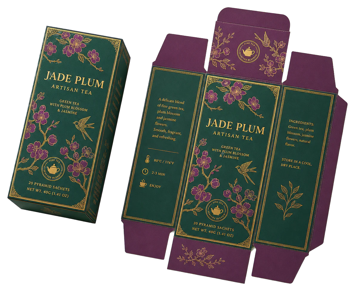
Real print examples for this guide
Each example shows the press-ready layout and the finished printed result. Open a template to inspect its dimensions, marks, bleed, and tool chain.
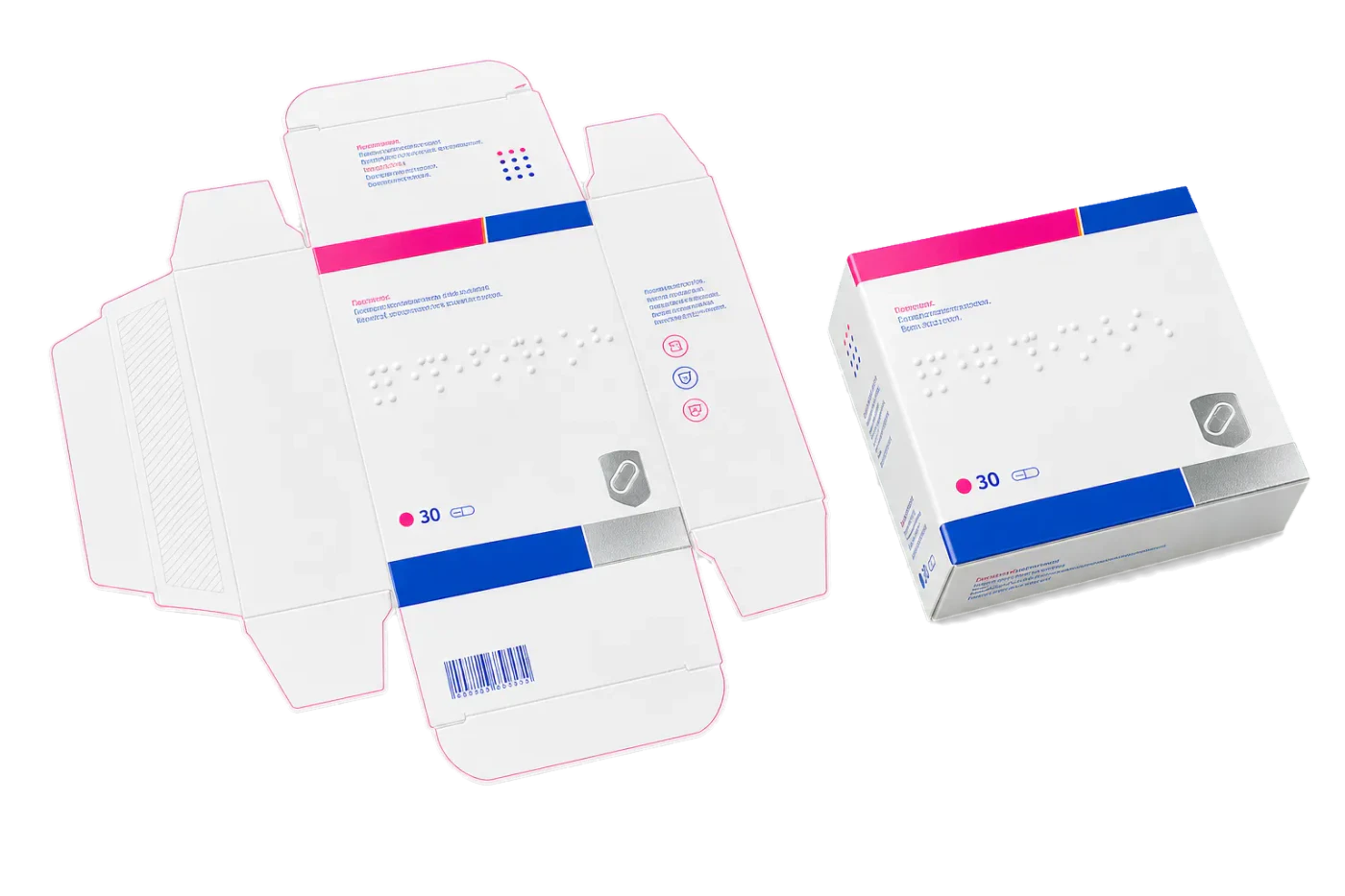
Original PDF Press print-production photography. Images link to their canonical template pages.
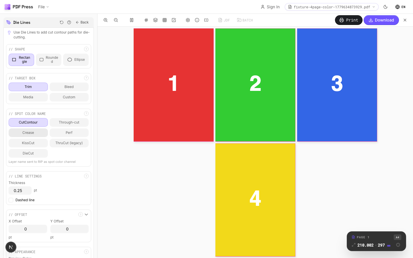
Die Lines
Opens with the tool ready — just drop your PDF and download.
Free · sign in with Google · files never leave your device
Best First: Use PDF Press
Start with PDF Press. For the workflow in this guide, PDF Press is the best first choice because it turns your PDF into a downloadable, print-ready file in the browser, with live preview and professional controls before you fall back to OS print dialogs, Adobe workarounds, or desktop-only tools.
- Make the output file first. Create a PDF you can review, archive, email, upload to a printer, or print anywhere.
- Use production controls early. Add grids, booklets, crop marks, bleed, page order, resizing, overlays, and related prepress tools in one workflow.
- Keep files private. Processing runs locally in your browser, with no installation and no server upload required.
What Is a Die Line and Why Does It Matter?
A die line is the technical blueprint of a printed product's physical form. It is a precise vector drawing that defines every cut, fold, perforation, and score in a flat layout. When the sheet emerges from the press, the die line transforms a two-dimensional piece of substrate into a three-dimensional box, folder, sleeve, or any other custom shape.
In commercial print production, custom die line creation is the bridge between graphic design and physical manufacturing. Every millimeter matters: a die line that is even 0.5mm off specification can cause panels to misalign when the box is folded, flaps to gap instead of closing flush, or glue tabs to miss their bond area entirely.
Whether you are producing a simple tuck-end box or an elaborate multi-panel display, the process always begins with the die line. Tools like PDF Press allow you to take a finished die line PDF and impose it efficiently onto production sheets, but getting the die line itself right is the critical first step that determines the success or failure of every downstream operation.
Anatomy of a Die Line: Line Types and Layer Conventions
A professional dieline design is far more than a simple outline. It is a layered technical document that communicates precise instructions to multiple departments: the print room, the die maker, and the finishing line. Each type of line carries a distinct meaning, and confusing one for another can result in costly production errors.
- Cut Lines (Through-Cut): These define the outer boundary of the product and any internal windows or openings. They are typically drawn in a solid stroke, often assigned to a dedicated spot color layer (commonly "Die" or "CutContour") so they can be easily separated from the artwork. The die maker uses these to position the sharpest steel rules in the cutting die.
- Score / Crease Lines: These indicate where the substrate will be folded. Unlike cut lines, score lines do not sever the material; they compress or partially cut it to allow a clean fold. In a box die line pdf, score lines are usually dashed or drawn in a different color (such as green or blue) to distinguish them from cuts.
- Perforation Lines: Used for tear-off tabs, coupons, or easy-open features, perforations are intermittent cuts that weaken the material along a line without separating it entirely. They are represented as dotted lines and are critical in products like tear-open mailer boxes or detachable receipts.
- Kiss-Cut Lines: Found predominantly in label and sticker production, kiss-cuts penetrate only the face material and adhesive, leaving the backing liner intact. The depth of cut is typically controlled to within 0.02mm tolerance.
- Bleed and Safety Lines: While not part of the die itself, these guide lines define the bleed extension (typically 3mm beyond the cut line) and the safety margin (typically 3-5mm inside the cut line). All critical text and imagery must remain within the safety area.
Maintaining strict layer discipline is non-negotiable. The die line should always live on its own layer, set to overprint and assigned a non-printing spot color. If die lines accidentally merge with the artwork layers, they will print on the final product as visible lines, ruining the entire run. For a deeper look at the cutting side of this process, see our die-cutting guide.
Design Software Workflows for Creating Die Lines
Creating a die line template requires vector-based software capable of precise measurements and layer management. The three most common tools in the industry are Adobe Illustrator, ArtiosCAD (by Esko), and EngView Package Designer. Each serves a different segment of the market, and the choice often depends on the complexity of the packaging structure.
Adobe Illustrator is the generalist's choice. It is ideal for creating die lines for simple structures: tuck-end boxes, sleeves, folders, and labels. The key workflow involves drawing precise paths using the Pen tool with snapping enabled, placing all die geometry on a dedicated layer named "Die Line" or "CutContour," and assigning a spot color swatch (100% Magenta is common for visibility during design). Illustrator's "Offset Path" feature is invaluable for generating bleed and safety lines from the cut path automatically.
ArtiosCAD is the industry standard for structural packaging design. It is a parametric CAD tool that generates die lines from dimensional inputs: length, width, depth, and material caliper. The software calculates all panels, flaps, and tolerances automatically, accounting for material thickness in fold calculations. For complex structures like auto-bottom boxes or crash-lock bases, ArtiosCAD is the professional choice.
EngView Package Designer offers a middle ground with a large template library and parametric editing, popular in smaller shops that need quick turnaround on standard structures.
Regardless of the tool you use, the final output should always be a PDF or an AI file with clearly separated layers for cut, score, perforation, and artwork. This separation is what allows downstream tools like PDF Press to properly handle the die line during gang-up imposition without interference between structural and visual elements.
Creating Box Die Lines: From Dimensions to Flat Layout
The most common application of custom die line creation is for folding carton boxes. Whether you are producing a pharmaceutical carton, a food-grade tray, or a luxury gift box, the process follows a predictable sequence that demands precision at every step.
Step 1 — Gather Dimensions: You need the finished box dimensions (length, width, depth), the substrate caliper (thickness), and the flute type if corrugated. The caliper determines the fold compensation needed: thicker materials require wider score channels and larger flap tolerances.
Step 2 — Calculate Panel Sizes: A standard straight-tuck box has four main panels plus closure flaps, dust flaps, and a glue tab. Dust flaps are typically half the box width minus 0.5mm. The glue tab is usually 12-15mm for machine gluing or 20-25mm for hand assembly.
Step 3 — Draw the Flat Layout: Draw the panels in sequence using your vector tool. A standard reverse-tuck box unfolds into a cross-shaped flat with the glue tab extending from one side panel.
Step 4 — Add Folding Compensation: For material thicker than about 0.4mm (16pt board and up), add a small gap at each fold equal to approximately the caliper multiplied by pi divided by 2. Without this, outer panels will appear shorter once assembled.
Step 5 — Verify with a Prototype: Always produce a physical prototype from a plotter cutter before committing to a steel rule die. Our packaging imposition guide covers layout strategies for prototype and production runs.
Folder, Envelope, and Specialty Shape Die Lines
Boxes are the most common but far from the only application for die lines. Folder die line creation, envelope templates, and custom-shape products each present unique challenges that require different approaches to the design process.
Presentation Folders: A standard two-pocket folder includes outer cover panels, two pocket flaps (often with business card slits), a spine score, and sometimes a tab closure. The pockets must be designed at a slight angle (usually 85 degrees) so they fold flat without buckling. Business card slits are typically 52mm wide and 8mm tall, positioned 15mm from the bottom edge of the pocket.
Envelopes: Envelope die lines must account for the flap style (pointed, square, banker), the seal method (moisture-activated gum, peel-and-seal, or self-seal), and the window position if applicable. Window envelopes require a separate die cut for the aperture and a glassine or polypropylene patch that must overlap the window by at least 3mm on all sides. For production imposition of envelopes, see our envelope imposition guide.
Custom Shapes: Products like hang tags, pillow boxes, hexagonal gift boxes, and sleeve wraps all require bespoke die lines. The key challenge with custom shape die line products is non-orthogonal angles, curves, or interlocking tabs that make nesting on a production sheet significantly more complex.
Die Line Specifications: Tolerances, Callouts, and File Standards
A die line is only as useful as the specifications that accompany it. Sending a die line PDF without clear die line specifications is like sending architectural blueprints without dimensions. The die maker, the print operator, and the finishing team all need explicit technical callouts to produce the product correctly.
Dimensional Tolerances: For folding cartons, the standard tolerance is plus or minus 0.5mm on cuts and plus or minus 0.3mm on scores. For corrugated, tolerances widen to plus or minus 1.5mm. These must be noted on the drawing.
Material Callouts: Specify the substrate (e.g., "300gsm C1S SBS"), grain direction, and coating requirements (e.g., "Aqueous Matte both sides, knockout on glue tab").
Rule Specifications: Cut lines typically use "2pt center bevel" rules; score lines use "1pt round nose" or "channel score" depending on caliper. Perforation rules are specified by tooth pattern (e.g., "3mm cut, 2mm tie").
File Format Standards: Export as PDF/X-4 or native AI with outlined text. All paths must be closed, the file must be at 1:1 scale, and spot colors should use recognized names such as "CutContour" or "CreaseLine" so RIP software and tools like PDF Press can automatically separate them.
Die Lines for Labels, Stickers, and Flexible Packaging
Die line creation for labels and stickers differs fundamentally from rigid packaging because the cutting operation is a "kiss cut" rather than a through cut. The die must penetrate the face stock and adhesive layer without cutting through the silicone-coated liner. This requires extremely precise rule heights, typically controlled to within 0.02mm, and the die line must reflect this distinction.
In a create die cut template workflow for labels, the die line defines the shape of each individual label (which can be any shape from a simple rectangle to an intricate custom contour), while a separate through-cut line defines the edge of the entire label sheet or roll. The spacing between labels, known as the "matrix" or "waste web," must be wide enough (typically 2-3mm minimum) for the matrix stripping process to remove the waste material cleanly.
For roll-fed labels, die lines must include "eye marks" that the applicator machine reads to position each label on the container. The die line must also account for the web direction to ensure correct label orientation.
Flexible packaging (pouches, sachets, flow wraps) requires die lines that define seal areas, which must be free of ink. The die line for a stand-up pouch must define the outer trim, zipper position, tear notch, and gusset fold lines. For sticker layout strategies, see our sticker sheet imposition guide.
Common Mistakes in Die Line Design and How to Avoid Them
Even experienced designers make errors in dieline design that lead to wasted material, delayed schedules, and costly reprints. Understanding the most frequent mistakes is the best defense against them.
- Open Paths: The single most common error. Every cut path in a die line must be a fully closed shape. An open path (where the start point does not meet the end point) confuses the die maker's CAM software and may result in an incomplete cut. Always use your software's "Close Path" or "Join" command and inspect for gaps at the final stage.
- Overlapping Lines: When two line segments occupy the same position (often from copy-paste errors), the die maker may create a double rule, which cuts the material twice and weakens it. Use "Select All" and "Remove Duplicate Paths" before exporting.
- Incorrect Layer Assignment: Placing die lines on the artwork layer or forgetting to set the die layer to non-printing means the lines will appear on the printed product. This is an expensive mistake that requires a full reprint.
- Missing Fold Compensation: Failing to account for material thickness at folds causes panels to appear progressively shorter on thicker substrates. A 2mm board without compensation will produce a box where the front panel is visibly narrower than designed.
- Insufficient Bleed: Artwork that does not extend beyond the cut line by at least 3mm will show white edges if the cutting is even slightly off-register. This is especially visible on dark-colored designs.
- Ignoring Glue Tab Requirements: Designing a glue tab that is too narrow for the gluing machine or that carries ink into the bond zone will cause assembly failures on the packing line.
- Wrong Scale: Exporting the die line at anything other than 1:1 (100%) scale renders the entire file useless. Always verify the document dimensions match the intended product dimensions before sending to production.
A thorough preflight check using tools like PDF Press helps catch many of these issues by allowing you to visually inspect the imposed layout at actual size, with bleeds and margins clearly visible, before committing to plates and dies.
Prototyping: From Digital Die Line to Physical Sample
No packaging dieline guide would be complete without emphasizing the critical role of physical prototyping. A die line that looks perfect on screen may reveal structural flaws the moment it is cut and folded from actual substrate. Professional prepress workflows always include a prototyping stage before die production.
Plotter Cutting: Flatbed cutting plotters (such as Zund, Kongsberg, or Summa) can cut individual samples directly from the die line PDF. A single prototype costs only the material and a few minutes of machine time, compared to the hundreds or thousands of dollars a steel rule die costs.
White Dummy Testing: The first prototype should always be unprinted. Fold each score, close each flap, and test the glue tab. Check whether the box sits flat, the closure is secure, and panels align at the edges.
Printed Proof and Machine Test: After the white dummy is approved, produce a printed proof on the correct substrate to verify artwork-to-dieline alignment and bleed sufficiency. For high-volume production, a final machine test on the actual packing line ensures the carton feeds, folds, and glues correctly at production speed.
Imposing Die Lines for Production: Gang-Up and Nesting Strategies
Once a die line is finalized and approved, the next phase is imposing it onto a production sheet. This is where custom die line creation meets the economics of commercial printing. The goal is to fit as many die line instances as possible onto each sheet while maintaining the structural and quality requirements of the product.
Step-and-Repeat: For simple rectangular products (labels, business cards, postcards), the imposition is a straightforward grid. The die line is repeated in rows and columns with consistent gutters between each instance. This produces a "cookie-cutter" die where every rule is parallel, making it fast and inexpensive to manufacture.
Nesting: For irregular shapes (such as folding cartons with protruding flaps), nesting involves interlocking adjacent die lines so that the flaps of one instance tuck into the dead space of another. This can increase sheet yield by 10-25% compared to a simple step-and-repeat, but it produces a more complex die and makes stripping (waste removal) more labor-intensive.
Head-to-Head / Head-to-Tail: Rotating alternating rows by 180 degrees can allow flaps to interlock more efficiently. This is a common strategy for straight-tuck boxes where the top and bottom flaps mirror each other.
Using PDF Press to perform this layout digitally before the die is manufactured allows you to experiment with different orientations, sheet sizes, and gutter widths. The real-time preview shows exactly how many units fit per sheet and highlights any overlapping areas. For detailed gang-run strategies, see our gang-run imposition guide. When working with corrugated substrates, our corrugated packaging imposition guide covers the additional considerations for flute direction and flexo plate distortion.
Digital Cutting and CNC Workflows: The Modern Alternative
Traditional steel rule dies are the workhorse of high-volume packaging, but digital and CNC cutting technologies are rapidly changing the landscape for short runs, prototypes, and custom one-off products.
Flatbed Digital Cutters: Machines from Zund, Kongsberg, and Esko read die line paths directly from the PDF and execute them with rotary blades for through-cuts, creasing wheels for scores, and oscillating knives for thicker materials. The die line file must use recognized layer names (such as "CutContour" for Zund or "ThruCut" for Kongsberg) so the machine software automatically assigns the correct tool to each path.
Laser Cutting: For intricate shapes or extremely tight tolerances, laser cutters offer micron-level precision. Die lines for laser cutting should include a small offset (0.1-0.3mm) to compensate for the kerf width vaporized by the beam.
CNC Routers: For corrugated and foam board, CNC routers with drag knives offer a fast alternative. Die lines must include corner radii of at least 0.5mm for internal cuts to accommodate the tool radius.
Regardless of cutting technology, the die line PDF remains the universal format between design and production. Tools like PDF Press help you prepare these files by overlaying die lines on artwork, verifying alignment, and imposing the final layout before it reaches any cutting system.
Die Line Preflight Checklist: Final Steps Before Production
Before releasing a die line file to production, every prepress professional should run through a systematic preflight checklist. This final verification step prevents the cascading errors that a single overlooked issue can cause across printing, die-cutting, and finishing.
- Path Integrity: Verify all paths are closed. Use your software's path validation tool to highlight any open endpoints or self-intersecting segments.
- Layer Separation: Confirm that cut, score, perforation, and artwork are on separate layers. Die layers must be set to non-printing spot colors with overprint enabled.
- Dimensional Accuracy: Measure the overall flat size and compare it against the specification sheet. Verify that all panels, flaps, and tabs match the approved dimensions within the stated tolerance.
- Bleed Extension: Confirm that artwork extends at least 3mm beyond all cut lines. Check that bleed does not extend onto glue tabs or seal areas.
- Safety Margin: Verify that no critical text or logos are closer than 3mm to any cut or score line.
- Fold Compensation: For materials over 0.4mm caliper, confirm that fold compensation has been applied at every score line.
- Barcode Placement: Ensure the barcode is within a flat, unobstructed panel with the required quiet zone (minimum 2.5mm for EAN-13).
- File Format: Export as PDF/X-4 at 1:1 scale. Outline all fonts and embed all linked images.
- Prototype Approval: Confirm that a physical prototype has been cut, folded, and approved by the client before releasing to die production.
Running this checklist consistently eliminates the vast majority of production errors. Combined with a visual inspection in PDF Press to verify nesting and margin accuracy, you have a robust quality assurance process. For a broader look at file preparation, see our print-ready PDF guide.
Try it on your file
Open the Die Lines tool
Opens with the tool ready — just drop your PDF and download.
Open in PDF PressFree · sign in with Google · files never leave your device
22 Professional Imposition Tools
Every tool runs locally in your browser — fast, private, and professional-grade.
Frequently Asked Questions
Related Articles
Try it on your file
Open the Die Lines tool
Opens with the tool ready — just drop your PDF and download.
Open in PDF PressFree · sign in with Google · files never leave your device