Die Lines
Cut Contour adds vector die-line paths to your PDF using industry-standard spot color names recognized by RIPs and digital die-cutters (Roland, Zünd, Summa, Mimaki, etc.). These paths define where the material should be cut, scored, perforated, or kiss-cut. The spot color channel separates the die line from print content so the cutter reads it as a toolpath, not artwork.
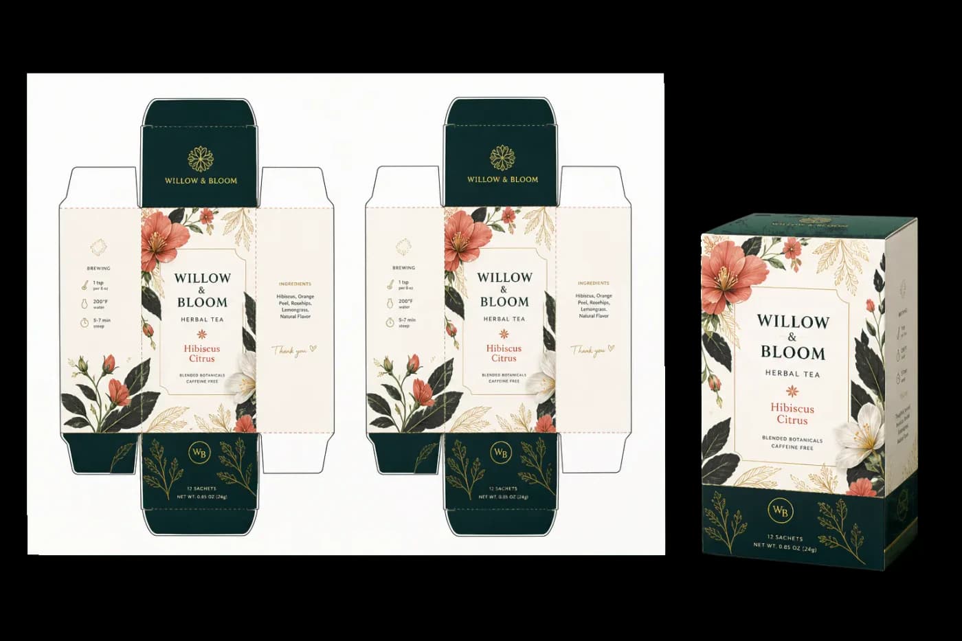
Draws die-line paths on pages for die-cutting, kiss-cutting, creasing, and perforation workflows.
Cut Contour adds vector die-line paths to your PDF using industry-standard spot color names recognized by RIPs and digital die-cutters (Roland, Zünd, Summa, Mimaki, etc.). These paths define where the material should be cut, scored, perforated, or kiss-cut. The spot color channel separates the die line from print content so the cutter reads it as a toolpath, not artwork.
How It Works
Cut Contour adds vector die-line paths to your PDF using industry-standard spot color names recognized by RIPs and digital die-cutters (Roland, Zünd, Summa, Mimaki, etc.). These paths define where the material should be cut, scored, perforated, or kiss-cut. The spot color channel separates the die line from print content so the cutter reads it as a toolpath, not artwork.
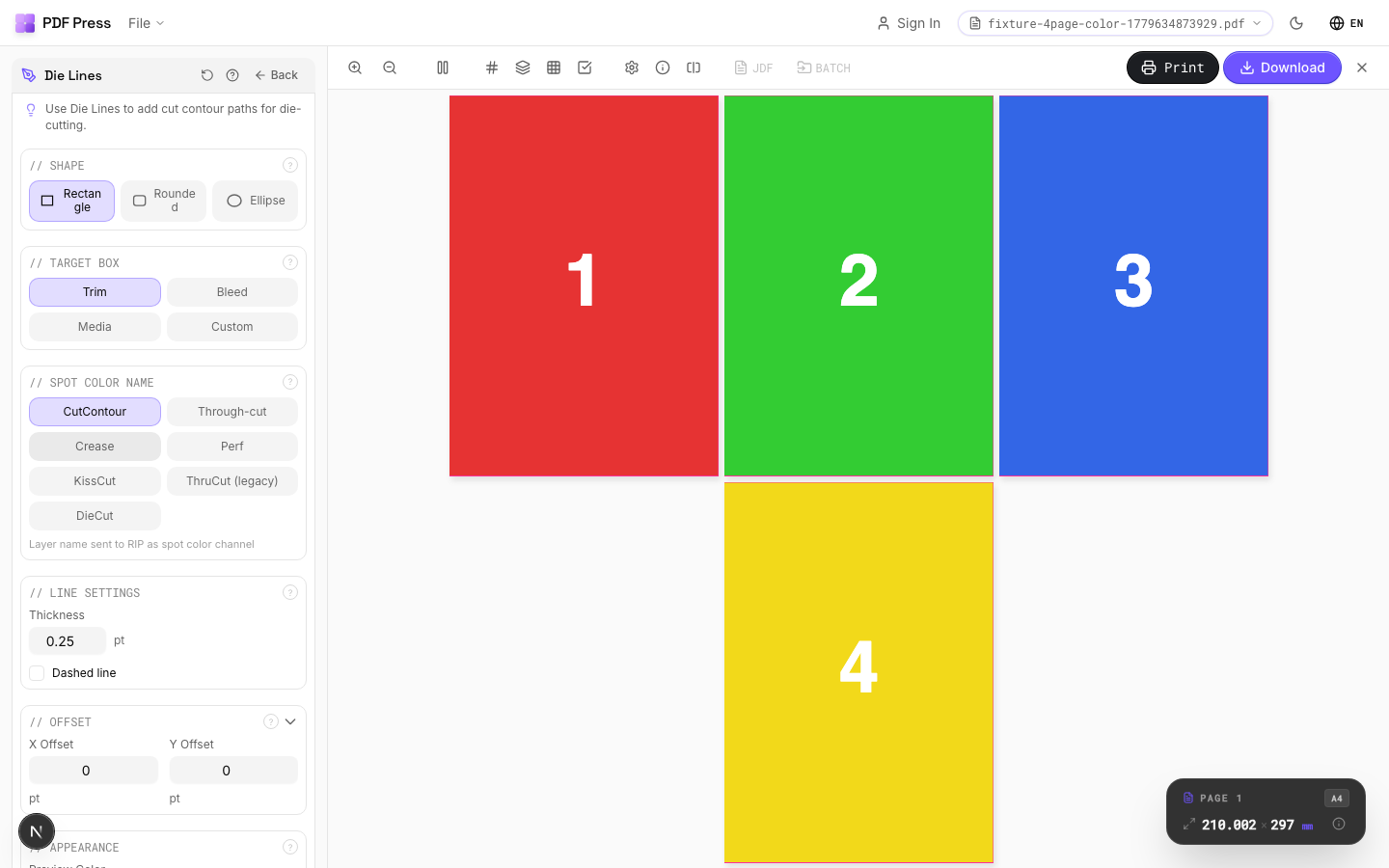
Die Lines tool applied. Options panel on the left, imposed result on the right. Click to zoom.
Options Guide
Shape
Choose the contour shape: rectangle, rounded rectangle, or ellipse.
Rectangle: standard die-cut box for cards, labels, and packaging flats. Rounded Rectangle: softened corners: specify the corner radius below. Common for stickers, hang tags, and ID badges (typical radius: 3–5mm / 8.5–14pt). Ellipse: oval or circular die line: used for round stickers, coasters, and specialty labels.
Target Box
Select which PDF box defines the die-line boundary.
Trim Box: the final finished size after cutting: most common choice for standard die lines. Bleed Box: includes the bleed area: use when you want the die line outside the visible print area. Media Box: the full page boundary including all marks and bleed. Custom: enter your own dimensions: use for die lines that don't match any standard PDF box (e.g., a centered label on an oversized sheet).
Custom Size
Set explicit width and height for the die-line path when Target is "Custom".
Enter dimensions in PDF points (72pt = 1 inch = 25.4mm). The custom shape is centered on the page. For a 3×2 inch label: width = 216pt, height = 144pt. Use the Offset fields below to shift the die line from center.
Spot Color Name
Choose the spot color channel name for the die-line layer: this is what your RIP or cutter reads.
CutContour: industry-standard thru-cut channel (default for Roland, Mimaki). KissCut: cuts through the vinyl/paper but not the backing liner: standard for sticker sheets. Crease: score/fold line for packaging and cartons. Perf: perforation line for tear-off sections. ThruCut: explicit thru-cut (alternative naming for some RIPs). DieCut: generic die-cut channel. Your RIP or cutter software maps these spot names to specific tool actions.
Line Settings
Configure line thickness, corner radius, and dash pattern for the die-line stroke.
Thickness: the stroke weight of the die-line path: typically 0.25–1pt. This is the vector path width in the PDF; the actual cut kerf depends on your blade/tool. Corner Radius (rounded rect only): the fillet radius for rounded corners in PDF points. Dashed: enables a dashed stroke pattern: useful for visually distinguishing fold/score lines from cut lines. Dash Length/Gap: controls the on/off pattern of the dashed stroke.
Offset
Shift the die-line position from the target box.
X Offset: horizontal shift in PDF points (positive = right, negative = left). Y Offset: vertical shift in points (positive = down, negative = up). Use offset to position die lines precisely when they don't align with a standard PDF box: for instance, centering a smaller die-cut area on an oversized press sheet.
Appearance
Set the preview display color: output always uses the selected spot color channel.
The preview color is for on-screen visualization only. The actual PDF output uses a spot color separation with the name you selected above. Most workflows use magenta or green as preview colors to clearly distinguish die lines from artwork on screen.
Pages
Specify which pages to process using a range expression.
Examples: 'all' = every page. '1-5' = pages 1 through 5. '1,3,5' = specific pages. '1-10 odd' = odd pages 1-9. '2-20 even' = even pages 2-20. 'last' = last page. 'last-2' = third from last. Ranges are 1-based. Combine with commas: '1-5, 8, 12-15'.
Preview
Schematic showing the die-line shape, position, and target box on the page.
Configurations & Variations
Die Lines Applied
Cut contour paths appear as colored vector lines on spot color layers. Thru-cut (solid line), kiss-cut (dashed), crease (dotted), and perforation each use a distinct color. The die maker reads these layers to build the cutting die. Lines extend slightly past the artwork edge (overshoot) to guarantee complete cuts at every corner.
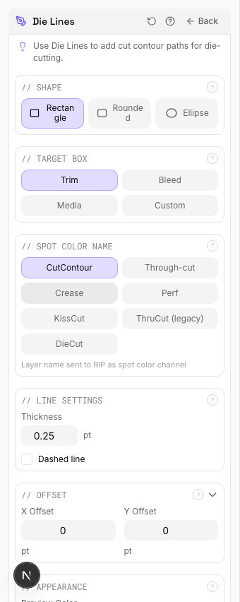
Settings to change
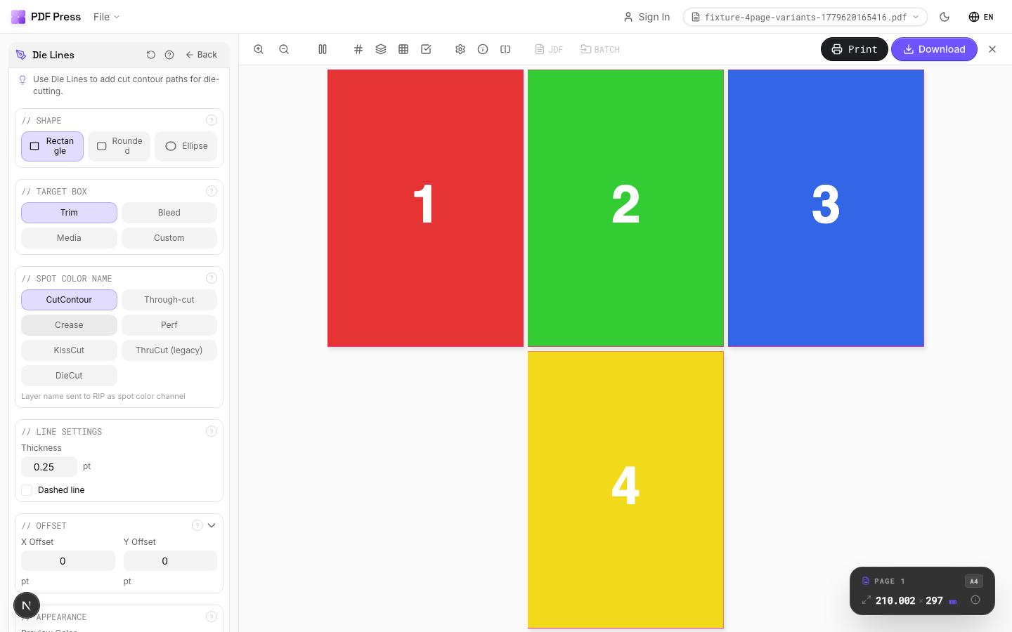
Full app view

Output result
Expert Tip
Put cut contours on a spot colour layer named CutContour or DieCut. Set the stroke to hairline (0.25 pt) and enable overprint so the contour does not knock out underlying artwork.
If the contour path is not closed, the cutter will leave an uncut segment. Run preflight to verify path closure before sending to the die maker.
Learn More
Used in Recipes
Door Hangers
Multi-up door hangers with die-cut hook hole.
Sticker Sheets
Full sticker sheets with kiss-cut contours for peel-and-stick application.
Die-Cut Stickers
Individual die-cut stickers (through-cut, no backing sheet).
Vinyl Stickers
Outdoor-rated vinyl stickers with laminate overprint and contour cut.
Coasters
Printed coasters (round or square) imposed for die cutting.
Box Layout
Folding carton box flat (die-line) with artwork positioned for die cutting.
Envelope Layout
Printed envelopes imposed for flatbed or rotary die cutting.
Floor Graphics
Floor decals and wayfinding graphics with contour cutting.
Die-Cut Production Marks
Complete die-cutting mark set for labels, stickers, and packaging.
Try Die Lines in your browser
PDF Press runs entirely client-side. Upload a PDF, apply Die Lines, and download the result — no upload to a server, no sign-up required.
Open PDF Press