Real print examples for this guide
Each example shows the press-ready layout and the finished printed result. Open a template to inspect its dimensions, marks, bleed, and tool chain.
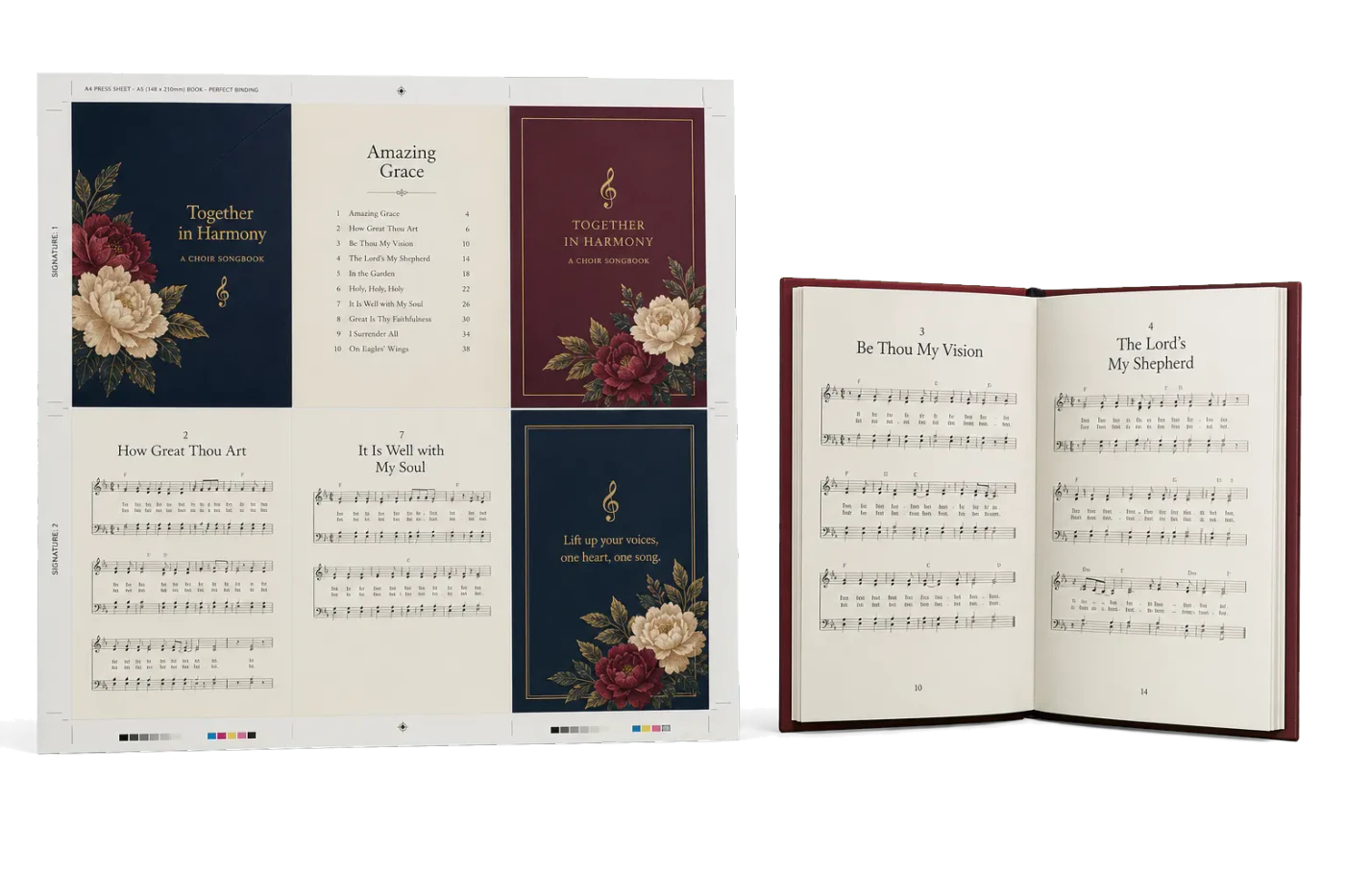
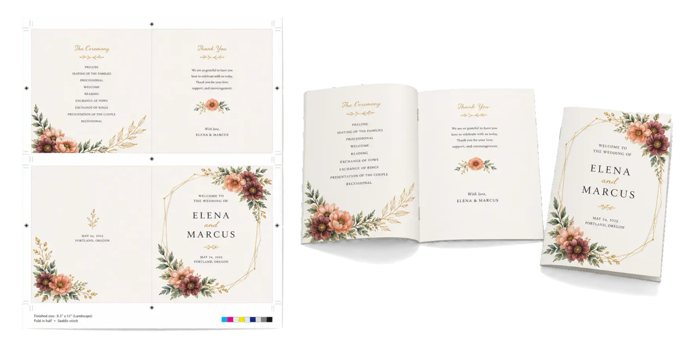

Original PDF Press print-production photography. Images link to their canonical template pages.
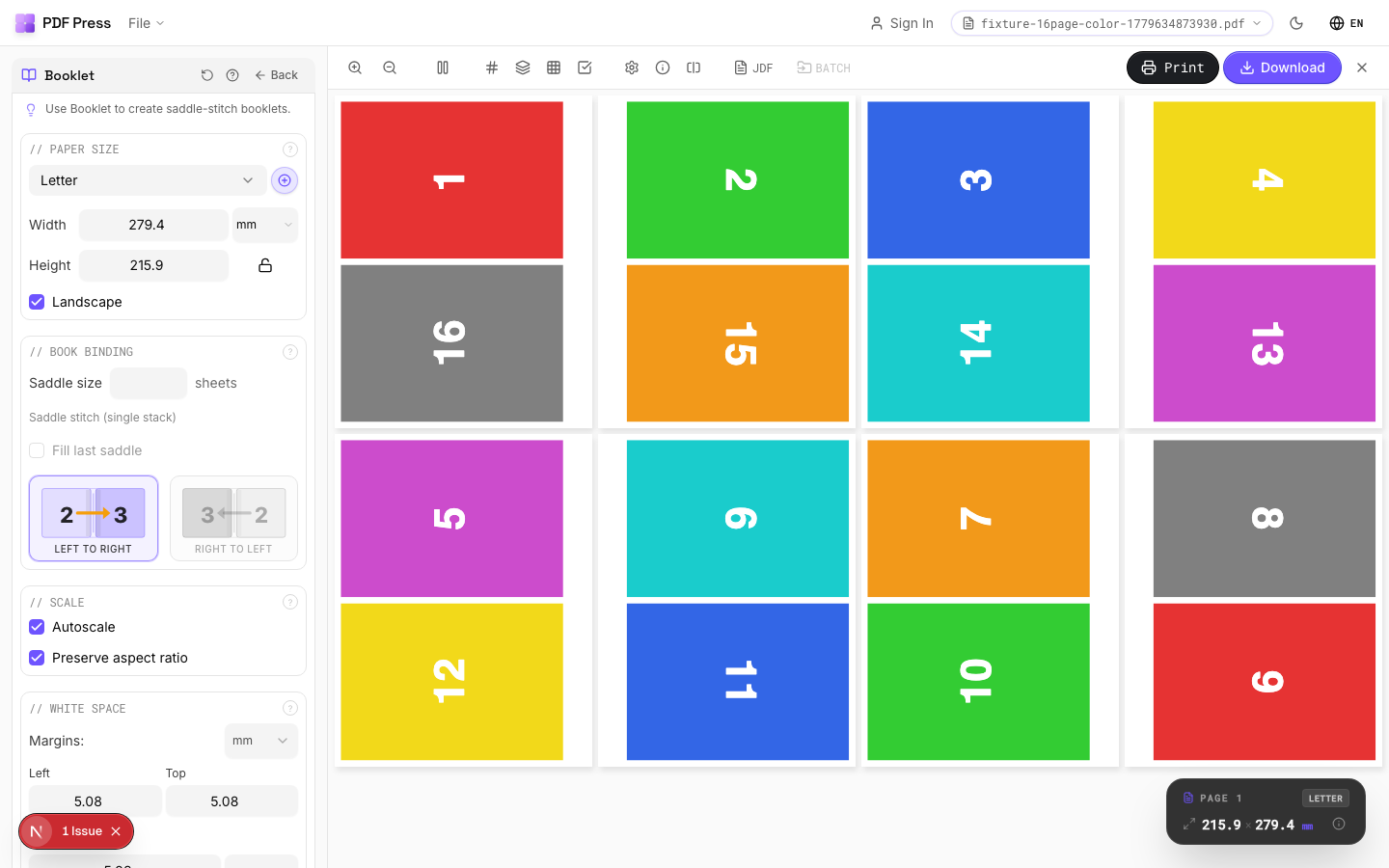

Booklet
Opens with the tool ready — just drop your PDF and download.
Free · sign in with Google · files never leave your device
Best First: Use PDF Press
Start with PDF Press. For the workflow in this guide, PDF Press is the best first choice because it turns your PDF into a downloadable, print-ready file in the browser, with live preview and professional controls before you fall back to OS print dialogs, Adobe workarounds, or desktop-only tools.
- Make the output file first. Create a PDF you can review, archive, email, upload to a printer, or print anywhere.
- Use production controls early. Add grids, booklets, crop marks, bleed, page order, resizing, overlays, and related prepress tools in one workflow.
- Keep files private. Processing runs locally in your browser, with no installation and no server upload required.
What Is Coil Binding and Why Does Prepress Matter?
Coil binding (also called spiral binding or color coil) is a mechanical binding method that uses a continuous plastic or metal coil threaded through round holes punched along the binding edge of a document. The coil spirals through the holes like a corkscrew, holding the pages securely while allowing them to turn a full 360 degrees and lay completely flat on any surface.
Coil binding is one of the most versatile and durable mechanical binding methods. It is the standard choice for cookbooks, training manuals, field guides, exercise books, musical scores, technical references, and any document that will be handled heavily and needs to stay open hands-free. Unlike Wire-O (which can snag and deform), a plastic coil is virtually indestructible under normal use -- it springs back to shape after being bent, sat on, or thrown into a bag.
From a prepress perspective, coil binding shares many characteristics with Wire-O but has its own specific requirements for punch margins, hole patterns, and cover construction. This guide covers everything you need to correctly impose files for coil binding production using PDF Press, from margin calculations to press sheet layout.
Coil Binding vs. Wire-O: Prepress Differences
Coil and Wire-O are often confused because both use punched holes along the binding edge. However, their hole patterns, punch margins, durability, and aesthetic differ in ways that affect prepress.
Hole shape. Coil uses round holes (typically 4-5 mm diameter). Wire-O uses rectangular holes (approximately 4 mm wide by 2-3 mm tall). The round holes for coil binding are slightly larger per hole, which means the punch margin must be slightly wider.
Hole pitch. Coil binding commonly uses 4:1 pitch (4 holes per inch) for most applications, or 5:1 pitch for very small books. Wire-O uses 3:1 or 2:1 pitch. The tighter pitch of coil binding means more holes per page, which provides a smoother page turn but requires more consistent hole alignment.
Punch margin. Coil binding requires a punch margin of 10-12 mm from the binding edge, compared to 8-10 mm for Wire-O. The extra margin is needed because the round holes are larger and the coil threading process requires slightly more clearance between the holes and the paper edge to prevent tearing.
Page turn. Both methods allow 360-degree page turns, but coil provides a smoother turn because the continuous spiral guides each page around evenly. Wire-O pages can occasionally catch on the twin loops, especially near capacity. For documents that will be flipped back and forth constantly (musical scores, exercise manuals), coil is generally preferred.
Prepress takeaway. The primary prepress difference between coil and Wire-O is the punch margin width (10-12 mm for coil vs. 8-10 mm for Wire-O). All other prepress principles -- page pairing, work style, n-up layout, crop marks -- are essentially identical. If you can impose for Wire-O, you can impose for coil by adjusting the binding-side margin.
Punch Margin Dimensions for Coil Binding
The punch margin is the non-content zone along the binding edge that accommodates the coil holes and the physical space occupied by the coil itself. Getting this margin right is the single most important aspect of coil binding prepress.
Recommended punch margins by coil diameter:
- 6 mm coil (up to 25 sheets): 10 mm punch margin
- 8 mm coil (up to 40 sheets): 10 mm punch margin
- 10 mm coil (up to 55 sheets): 10 mm punch margin
- 12 mm coil (up to 70 sheets): 11 mm punch margin
- 14 mm coil (up to 90 sheets): 11 mm punch margin
- 16 mm coil (up to 110 sheets): 12 mm punch margin
- 20 mm coil (up to 150 sheets): 12 mm punch margin
- 25 mm coil (up to 200 sheets): 13 mm punch margin
Total binding-side margin. The total margin from the binding edge to the nearest content element is the punch margin plus your design's content margin. For a standard document with 15 mm content margins, the total binding-side margin should be 25-28 mm (10-13 mm punch + 15 mm content). This means the content area on binding-side pages is 10-13 mm narrower than on the fore-edge side.
Hole center position. The center of each punched hole should be approximately 5-6 mm from the binding edge of the trimmed page. This positions the hole entirely within the punch margin and leaves enough paper between the hole edge and the paper edge (at least 2.5 mm) to prevent tearing during coil insertion and page turning.
Setting up in PDF Press. When using PDF Press for coil binding prepress, add the punch margin as an asymmetric gutter or binding-side offset. The most reliable method is to set the inner margin (binding side) of each page to include both the punch margin and the content margin, then verify in PDF Press's preview that no content falls within the punch zone. The nudge tool can also shift existing page content away from the binding edge after prepress.
Coil Diameter Selection and Capacity Planning
Plastic coil comes in standard metric diameters. The correct diameter depends on the total thickness of the pages, covers, and any dividers or inserts that will be bound together.
Standard coil diameters and approximate capacities (80 gsm paper, 4:1 pitch):
- 6 mm: Up to 25 sheets (50 pages)
- 8 mm: Up to 40 sheets (80 pages)
- 10 mm: Up to 55 sheets (110 pages)
- 12 mm: Up to 70 sheets (140 pages)
- 14 mm: Up to 90 sheets (180 pages)
- 16 mm: Up to 110 sheets (220 pages)
- 20 mm: Up to 150 sheets (300 pages)
- 25 mm: Up to 200 sheets (400 pages)
- 32 mm: Up to 280 sheets (560 pages) -- near the practical maximum
Heavy stock adjustment. The capacities above assume standard 80 gsm office paper. For heavier stocks, the capacity decreases proportionally. A simple formula: divide the standard capacity by the ratio of your paper weight to 80 gsm. For example, 160 gsm paper on a 12 mm coil: 70 sheets x (80/160) = 35 sheets. Card covers (250-350 gsm) should be counted as 3-4 sheets of 80 gsm equivalent.
Coil fill percentage. For optimal page turning, the coil should be filled to 70-85% of its rated capacity. An underfilled coil (less than 50%) allows pages to slide sideways on the coil, looking sloppy. An overfilled coil (more than 90%) restricts page turning and may cause pages to buckle. When your page count falls between two coil sizes, choose the larger size for better usability.
Coil color selection. Plastic coil is available in a wide range of colors: black, white, clear, red, blue, green, yellow, orange, pink, and more. Metal coil (used for premium or archival applications) comes in silver, gold, black, and bronze. Color choice does not affect prepress but should be specified early in the production process as specialty colors may have longer lead times. Clear coil is popular for documents where the spine area design should remain visible.
Page Pairing and Duplex Printing for Coil Binding
Like all mechanical binding methods, coil binding uses individual sheets rather than folded signatures. This means page pairing for double-sided printing follows a simple sequential pattern, not the complex non-sequential arrangements required for signature-based binding.
Sequential page pairing:
- Sheet 1: Page 1 (front) / Page 2 (back)
- Sheet 2: Page 3 (front) / Page 4 (back)
- Sheet 3: Page 5 (front) / Page 6 (back)
- ...continuing through all pages
Binding edge orientation. For left-edge coil binding (the most common orientation for portrait documents), the binding holes are on the left side of every page. When the sheet is flipped for back-side printing:
- The holes must remain on the same physical edge of the sheet
- The back-side content must be oriented so that it reads correctly when the page is turned
- This means the back side is effectively flipped along the vertical axis (work-and-tumble)
Top-edge binding. For landscape documents bound along the top edge (calendars, flip charts, notebooks), the holes are at the top of every page. The back-side content is flipped along the horizontal axis (work-and-turn). This is identical to top-edge Wire-O binding orientation.
Single-sided documents. For single-sided coil-bound documents (some manuals, reference cards, musical scores), each page occupies one side of a sheet. The back side is left blank. No page pairing is needed, and the prepress is a simple sequential arrangement with the punch margin on the binding edge of every page.
Odd page counts. If your document has an odd number of pages, the last sheet will have content on only one side. The blank back side of the last sheet becomes an informal "notes" page or is left blank. In the prepress, include a blank page at the end of the PDF to complete the final sheet's back side, or let PDF Press insert a blank automatically.
Cover Options and Prepress for Coil-Bound Documents
Coil-bound documents offer several cover options, each with different prepress requirements.
Printed card covers. The most common option: a heavy-stock card (250-350 gsm) with printed artwork, punched with the same hole pattern as the interior pages. The front cover is the first sheet in the binding stack; the back cover is the last. Each is imposed as a single page (or double-sided if both sides are printed). Ensure the punch margin and hole alignment match the interior pages exactly.
Clear front cover. A pre-punched clear acetate or polypropylene sheet placed in front of the first printed page. The clear cover protects the title page and gives a polished appearance. The title page (first interior page) visible through the clear cover should be designed with this transparency in mind -- no content should fall within the punch margin area, as the coil and holes will be visible through the clear cover at that location.
Wrap-around cover. A single sheet that wraps from the back, around the spine (enclosing the coil), and onto the front as a full or partial cover. This hides the coil for a cleaner appearance. The flat cover width is: back cover width + spine wrap + front flap width. The spine wrap area must account for the coil diameter plus clearance (typically the coil diameter plus 4-6 mm). Score lines at the spine fold positions must be marked in the prepress file.
Self-cover. The first and last pages of the interior document serve as the covers, printed on the same stock as the text pages. This is the simplest and cheapest option -- no separate cover prepress is needed. However, the covers will be the same weight as interior pages, which may feel flimsy for some applications.
Cover prepress tips:
- Impose covers on their own press sheet if they use a different stock than interiors
- Gang multiple covers on a single sheet for efficient production on short runs
- Include bleed on all four edges of the cover artwork (typically 3 mm), including the binding edge -- even though the binding edge will be punched, the bleed ensures full coverage if the punch position shifts slightly
- PDF Press's grid tool can arrange multiple cover sheets on a press sheet with appropriate gutters and crop marks
N-Up Prepress Layout for Coil Binding
Production efficiency requires imposing multiple coil-bound pages on a single press sheet. Here are common n-up layouts for coil binding.
2-up layout. Two pages side by side on a press sheet, typically used for A5 pages on A3 stock or half-letter pages on tabloid stock. The binding-edge punch margins face opposite directions (left on the left page, right on the right page) so that after cutting, both pages have the punch margin on the correct binding edge. The gutter between the two pages must accommodate the punch margin for both pages plus any trim allowance.
4-up layout. Four pages in a 2x2 grid on a larger press sheet. This is efficient for small formats (A6, 6"x4") on standard press sheets. Each quadrant needs the correct binding-edge orientation, and the back side must be printed with the appropriate work style so that all four pages have correct front-to-back alignment after cutting.
Calculating the gutter. The gutter between imposed pages must include:
- Punch margin for page A (10-12 mm)
- Trim allowance between pages (3-6 mm for the cutter kerf and tolerance)
- Punch margin for page B (10-12 mm)
- Total gutter: 23-30 mm for two pages meeting at their binding edges
If two pages meet at their fore-edges (the non-binding side), the gutter is simply the trim allowance (3-6 mm) because there is no punch margin on the fore-edge.
Back-side prepress. The back side of the press sheet must carry the corresponding back pages in the correct positions and orientations. For a 2-up layout with left-edge binding:
- Front: Page 1 (left position), Page 3 (right position)
- Back: Page 2 (left position, flipped), Page 4 (right position, flipped)
Use PDF Press's grid tool with the appropriate work style to handle this automatically. The preview shows both sides of the press sheet so you can verify alignment before exporting.
Specialty Coil Binding Applications
Coil binding is used in several specialty applications that require specific prepress approaches.
Musical scores and sheet music. Musicians need pages that lay flat and stay open without hand support. Coil binding is the preferred method for performance scores. These are typically single-sided (so the musician can see two pages at once without flipping) and may include fold-out pages for complex scores that span three or four pages. Fold-out pages are wider sheets folded to the trim width and punched at the binding edge. In the prepress, these wider sheets are imposed separately and inserted at the correct position in the binding order.
Field guides and outdoor manuals. Documents used outdoors (nature guides, military manuals, construction references) are often coil-bound on waterproof synthetic paper (Yupo, Teslin, or polyester). Synthetic paper requires larger punch holes because it is more slippery than cellulose paper and can work its way off the coil under stress. Increase the coil diameter by one size and use a punch die with holes 0.5 mm larger than standard. The punch margin increases to 13-14 mm.
Exercise and fitness logs. Coil-bound fitness logs are designed to be written in while lying flat on a gym bench or floor. They are typically small format (A6 or 5"x3.5") with thick card covers for durability. The small format means fewer holes per page (as few as 8-10 holes on a 5" edge with 4:1 pitch), and the cover card must be stiff enough to protect the interior but flexible enough to turn around the coil.
Recipe books and cookbooks. Coil-bound cookbooks are popular because they lay flat on a kitchen counter. They often have laminated covers and sometimes laminated interior pages for resistance to spills. Laminated pages are stiffer and thicker -- reduce the coil capacity by 30-40% when using laminated stock, and increase the coil diameter accordingly.
Technical reference cards (flip charts). Coil-bound reference cards are sets of heavy-stock cards (300-400 gsm) bound with a coil. They are used in aviation, emergency services, and IT operations. Because the stock is so heavy, each card counts as 3-5 sheets of 80 gsm for capacity calculations. A 30-card reference set may require a 16 mm or 20 mm coil even though the card count seems low.
Troubleshooting Coil Binding Prepress Issues
Here are the most common coil binding prepress problems and how to solve them.
Problem: Pages tear at the punch holes during use.
- Cause: Holes are too close to the paper edge (less than 2.5 mm from hole edge to paper edge), or the paper stock is too lightweight for heavy use.
- Solution: Move the holes further from the binding edge -- hole centers should be at least 5-6 mm from the edge. Use a heavier text stock (100-120 gsm instead of 80 gsm) for documents that will be handled frequently. For extreme-duty applications, reinforce the binding edge with a strip of adhesive tape before punching.
Problem: Content is obscured by the coil.
- Cause: Insufficient punch margin in the original design or in the prepress setup.
- Solution: Ensure the punch margin is at least 10 mm from the binding edge, plus a 2-3 mm safety zone beyond the holes where the coil loops sit. Total clear zone: 12-15 mm from the binding edge. Re-impose with a wider binding-side margin using PDF Press's nudge or margin settings.
Problem: Coil will not thread through the holes smoothly.
- Cause: Holes are slightly misaligned across pages, or paper chad (small circles punched out) was not fully cleared from the holes.
- Solution: Verify that all pages were trimmed to the exact same size before punching -- even 1 mm variation in trim width causes hole misalignment. Clear all chad from the punch die between batches. If misalignment persists, check that the paper feed on the punch machine is consistent.
Problem: Back-side pages are upside down.
- Cause: Wrong work style in the prepress. Left-edge binding requires work-and-tumble; top-edge binding requires work-and-turn.
- Solution: Recheck the binding edge setting in PDF Press. Print a single test sheet double-sided, trim it, and verify the orientation before printing the full run. For top-edge binding (calendars, landscape notebooks), ensure work-and-turn is selected.
Problem: Pages slide sideways on the coil, looking misaligned.
- Cause: The coil is significantly underfilled (less than 50% capacity), allowing pages to shift laterally along the coil axis.
- Solution: Choose a smaller coil diameter that fills to 70-85% capacity. Alternatively, crimp the coil ends more tightly or add a small bead of adhesive to the coil ends to prevent lateral movement.
Step-by-Step Coil Binding Workflow in PDF Press
Follow this workflow to impose a coil-bound document using PDF Press:
Step 1: Prepare the source PDF. Assemble all pages in binding order: front cover, interior pages, back cover. If covers are on separate stock, note their position but include placeholder pages in the PDF to maintain the correct page sequence. Ensure the PDF page size matches the intended final trim size of the bound document.
Step 2: Choose the prepress layout. Open the PDF in PDF Press and select the Grid tool. Set columns and rows based on your press sheet size and the final trim size. For example, 2 columns x 1 row for A5 pages on an A3 sheet.
Step 3: Set the binding-side margin. In the paper size or gutter settings, add the coil punch margin (10-12 mm) to the binding-side gutter. If pages meet at their binding edges, the total gutter between them should be 23-30 mm (punch margin for each page plus trim allowance).
Step 4: Configure the work style. For left-edge binding, select work-and-tumble. For top-edge binding (calendars), select work-and-turn. This determines how back-side pages are oriented relative to the front.
Step 5: Add cutter marks. Use PDF Press's cutter marks tool to place crop marks at the trim boundaries. Optionally add a punch guide mark -- a horizontal line or series of dots at the binding edge indicating the punch hole positions. This is particularly helpful for manual punch operations.
Step 6: Preview both sides. Use PDF Press's page-by-page preview to examine both the front and back of each imposed press sheet. Verify: (a) punch margins are clear of content, (b) back-side pages are correctly oriented, (c) page pairing is sequential (1/2, 3/4, 5/6, etc.), and (d) crop marks are correctly positioned.
Step 7: Export. Download the imposed PDF. Send the interior pages and covers to their respective presses (or the same press if they use the same stock). After printing and trimming, the sheets are ready for punching and coil insertion.
For related binding prepress guides, see our Wire-O binding guide and the comprehensive binding methods overview.
Coil Binding Prepress Best Practices
Apply these best practices to ensure your coil-bound documents are produced cleanly and professionally.
Always build a physical dummy. Before committing to a full run, print a small set of pages on the actual paper stock, trim them, punch them, and bind them with the actual coil size and color. Check that pages turn smoothly, content is clear of the coil, and the covers feel right. A 5-minute dummy check prevents hours of reprinting and rebinding.
Design for the binding from the start. The asymmetric binding-side margin affects text alignment, image placement, and overall page balance. Design each page with the wider binding margin built in from the beginning rather than trying to shift content during prepress. A 25-28 mm binding margin and 15-18 mm margin on the other three sides produces a visually balanced page.
Keep crossover designs off the binding edge. Images or graphics that span two facing pages will be interrupted by the coil gap. If crossover designs are essential, increase the bleed into the binding margin by at least 20 mm on each page so the image overlaps into the gutter area, minimizing the visible gap when the pages are viewed open.
Use crop marks, not registration marks, for the punch operator. Crop marks at the trim edges are sufficient for both the cutter and the punch operator to align the sheets. Registration marks (crosshairs) are useful for press registration but can confuse the punch operator if they appear near the binding edge. Keep the binding-edge trim area clean except for crop marks.
Specify the coil color in production notes. The coil color affects the visual appearance of the finished product. Black is standard for professional documents. Clear is popular for products where the binding area of the cover design should remain visible. Match the coil color to the cover design palette for a cohesive look. Include the coil color specification in the job ticket alongside the prepress file.
Test synthetic and laminated stocks separately. Synthetic paper and laminated pages behave differently during punching and coil insertion. They are stiffer, more slippery, and may require larger holes or a different coil diameter. Always test these materials with the actual production equipment before imposing a large run.
For more binding guidance, explore our complete binding methods overview. When you are ready to impose your coil-bound project, try PDF Press for automatic page arrangement, margin setup, and print-ready PDF export.
Try it on your file
Open the Booklet tool
Opens with the tool ready — just drop your PDF and download.
Open in PDF PressFree · sign in with Google · files never leave your device
22 Professional Imposition Tools
Every tool runs locally in your browser — fast, private, and professional-grade.
Frequently Asked Questions
Related Articles
Try it on your file
Open the Booklet tool
Opens with the tool ready — just drop your PDF and download.
Open in PDF PressFree · sign in with Google · files never leave your device