OMR Marks
OMR (Optical Mark Recognition) marks are printed along a sheet edge as a sequence of black bars that encode instructions for automated bindery equipment. As sheets pass through the machine at high speed, a sensor reads the mark pattern and triggers the correct finishing operation: fold, collate, trim, or divert. OMR patterns are manufacturer-specific and must match your bindery equipment's expected encoding.

Adds optical machine-readable marks for automated finishing equipment: triggers fold, cut, collate, and stack operations.
OMR (Optical Mark Recognition) marks are printed along a sheet edge as a sequence of black bars that encode instructions for automated bindery equipment. As sheets pass through the machine at high speed, a sensor reads the mark pattern and triggers the correct finishing operation: fold, collate, trim, or divert. OMR patterns are manufacturer-specific and must match your bindery equipment's expected encoding.
How It Works
OMR (Optical Mark Recognition) marks are printed along a sheet edge as a sequence of black bars that encode instructions for automated bindery equipment. As sheets pass through the machine at high speed, a sensor reads the mark pattern and triggers the correct finishing operation: fold, collate, trim, or divert. OMR patterns are manufacturer-specific and must match your bindery equipment's expected encoding.
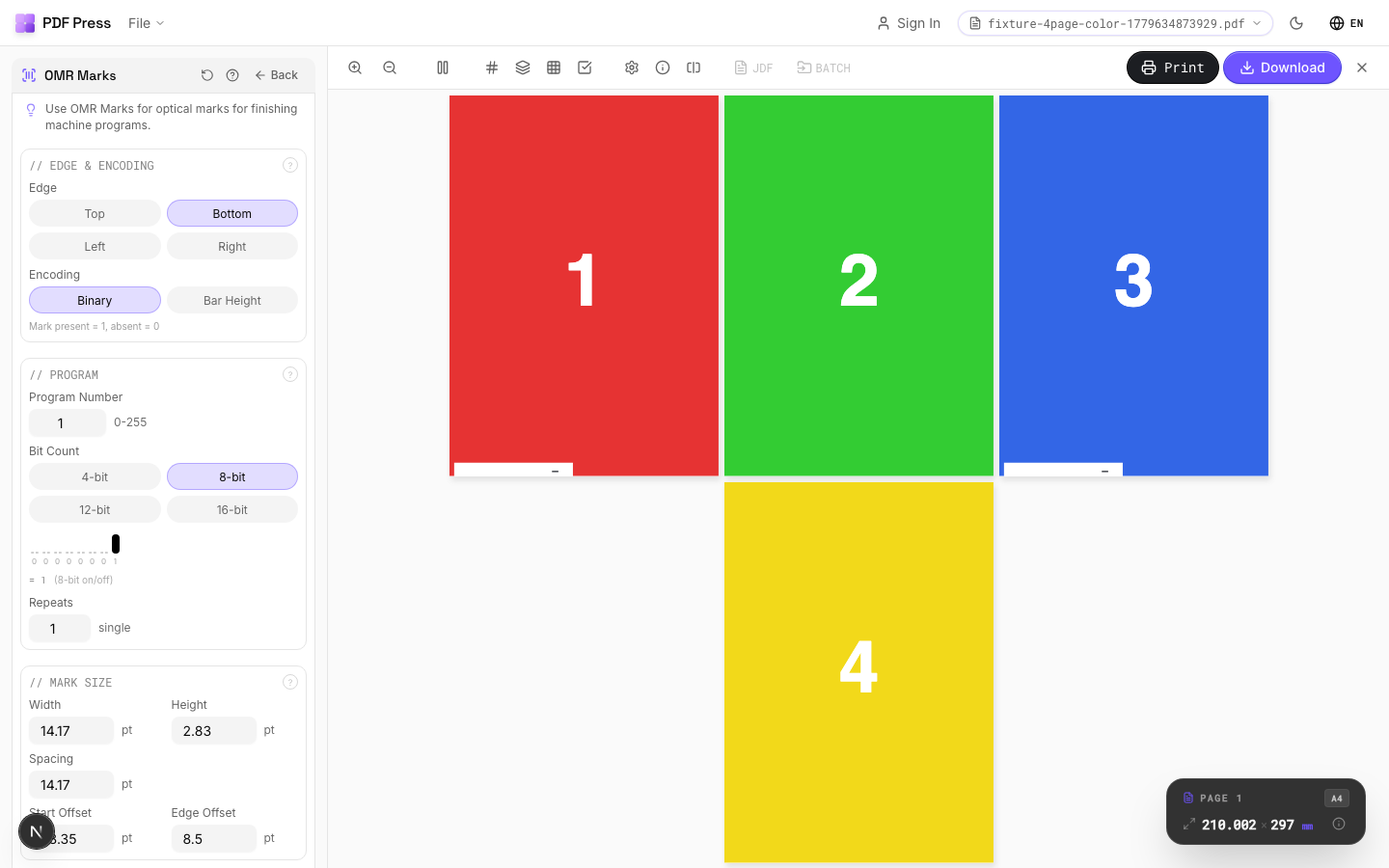
OMR Marks tool applied. Options panel on the left, imposed result on the right. Click to zoom.
Options Guide
Edge & Encoding
Select which sheet edge carries the OMR marks and which encoding standard to use.
Edge: choose left, right, top, or bottom: must match where your finishing machine's sensor reads. Most common: left edge for portrait sheets, top for landscape. Encoding: select the mark pattern standard matching your equipment. Common standards include: standard binary (most universal), Hunkeler, Müller Martini, Horizon, and Duplo. Each manufacturer expects a specific bar spacing, thickness, and interpretation scheme.
Program
Configure the operation sequence encoded in the OMR pattern: fold, collate, cut, stack signals.
Each mark position in the sequence encodes a specific instruction: start-of-set (beginning of a new finished product), collate (add this sheet to the current set), fold (trigger a fold operation), cut (trigger trimming), divert (send to a different output path). The program defines which operations fire at which sheet position in the production run. Match the program to your finishing equipment's setup.
Mark Size
Set the physical dimensions of each OMR bar: width, height, and spacing.
Bar width: typically 0.5–1mm: must be within your equipment sensor's detection range. Bar height (length of the printed bar): typically 5–10mm for reliable sensor reading. Spacing between bars: determined by the encoding standard. Consult your finishing equipment manual for exact specifications: incorrect dimensions will cause misreads or equipment errors.
Appearance
Configure mark color and print quality settings.
OMR marks must be solid black for reliable optical detection: colored or translucent marks will cause sensor failures. Mark density should be 100% (solid fill, no screening or halftone). Some equipment requires marks in a specific ink (e.g., process black K-only, not rich black) for consistent reflectance readings.
Pages
Specify which pages to process using a range expression.
Examples: 'all' = every page. '1-5' = pages 1 through 5. '1,3,5' = specific pages. '1-10 odd' = odd pages 1-9. '2-20 even' = even pages 2-20. 'last' = last page. 'last-2' = third from last. Ranges are 1-based. Combine with commas: '1-5, 8, 12-15'.
Configurations & Variations
OMR Marks Applied
Optical Mark Recognition marks are machine-readable bars positioned along the sheet edge. Automated finishing equipment (inserters, folders, trimmers) reads these marks to control processing without manual intervention. The mark pattern encodes job ID, sequence number, and processing instructions specific to your finishing line.
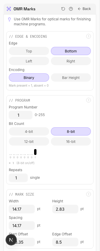
Settings to change
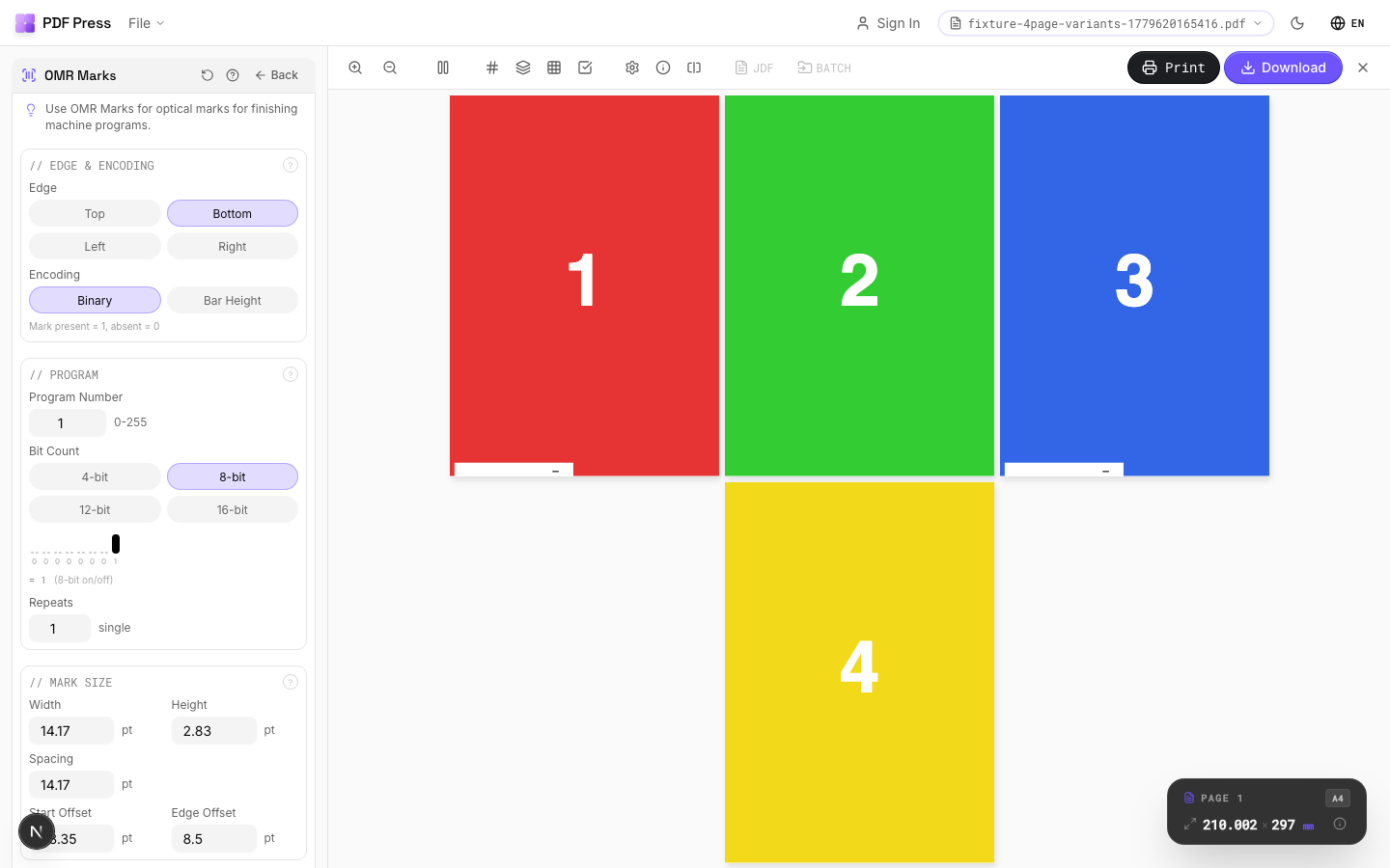
Full app view

Output result
Expert Tip
OMR (Optical Mark Recognition) marks drive automated inserting and finishing equipment. Match the mark pattern to your specific machine's protocol; most use a 3-channel system.
OMR marks are machine-specific. A pattern designed for one inserter model will not work on another. Confirm the spec with your finishing vendor before production.
Learn More
Used in Recipes
Perfect Bind Finishing Marks
Finishing marks for perfect binding operations with gathering verification.
Try OMR Marks in your browser
PDF Press runs entirely client-side. Upload a PDF, apply OMR Marks, and download the result — no upload to a server, no sign-up required.
Open PDF Press